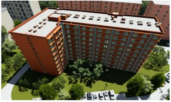
① Project Introduction
This project is situated in Gucun Town, Baoshan District, Shanghai, covering an area of 27,598.72 square meters with a total construction area of 71,389.87 square meters. The above-ground construction area accounts for 57,563.74 square meters, while the underground area covers 13,826.13 square meters. The development consists of six individual buildings, each with nine floors and a height of 27.7 meters. The structure is a reinforced concrete prefabricated design (see Figure 1).
② BIM Application
1) Comprehensive BIM Modeling
BIM software was utilized to model various building specialties, including structural elements, plumbing, electrical systems, and HVAC. The design process incorporated modular design principles, allowing spatial modules to be created within the BIM platform. This approach was further refined for interior decoration and detailed layouts of water and electrical pipelines. Early integration of modular spaces enabled a more standardized and efficient design process.
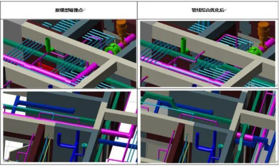
2) Clash Detection and Optimization
Using BIM analysis tools, collision detection was performed to identify conflicts among different specialties and components within the BIM model. This was carried out through both manual inspection and automated BIM software detection. A total of 23 issues were identified, as illustrated in Figure 2.
3) Production Material Lists
The BIM software automatically calculated material usage for the project, enabling comparisons of cost variations across different design schemes. This functionality supported designers in optimizing materials and budgets effectively.
4) Node Visualization Design
By linking the BIM model with the project schedule, a 4D construction simulation animation was created. This visual simulation allowed for rehearsal of construction sequences, clearly demonstrating the assembly process for each component. Complex nodes were visualized and explained within the BIM framework, helping workers understand component assembly order and the spatial relationships of steel bars and cast-in-place reinforcement nodes. This improved onsite assembly guidance and enhanced installation quality.
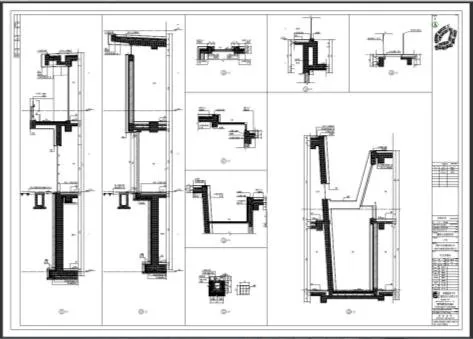
5) Drawing Generation
Revit software was used to generate drawings for the main building plans, elevations, sections, and component details with a single click. However, due to software limitations and user factors, some omissions and errors occurred in the initial drawings. These were subsequently refined and optimized using traditional 2D drawing software to ensure accuracy and compliance with construction requirements (see Figure 3).


Must log in before commenting!
Sign Up