This article is brought to you by the BIM Center of Guangdong Heavy Industry Institute.
Today’s tip: Creating custom doors and windows with GDL in ARCHICAD.
Note: There is no default shortcut key for this process.
To access the 3D projection settings, go to the menu bar: View > 3D View Options > 3D Projection Settings.
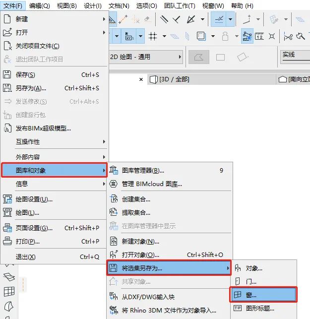
To save doors and windows to a specific location, navigate to: File > Gallery and Objects > Save Selection As > Windows.
Let’s start by opening ARCHICAD and drawing a custom window.
First, use the spline curve tool to outline the window shape. Then switch to the polyline tool, hold down the spacebar, and click on the drawn window outline to select it.
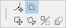
(The image above shows the location of the “polyline” tool.)
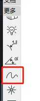
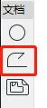
(The image above shows the position of the spline curve tool.)
Next, hold down the Shift key, click on the window outline, then click any black node on the outline. In the dialog box that appears, choose Offset All Edges. This will offset the window frame by the desired width.
(The above image highlights the location of the “Offset All Edges” option.)
Now, let’s draw the window frame using the board tool.
Select the board tool, set the material and thickness (for example, 300 mm). Then hold the spacebar and click on the outermost contour line of the window.
Select the drawn board, click any small black node, and in the pop-up dialog box choose Reduce from Polyhedron. Then hold the spacebar and click on the inner contour line. This method will effectively create the window frame.
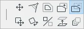
(The board tool is illustrated in the image below.)
(The image above shows the “Reduce from Polygon” option.)
Next, let’s add the window glass. Select the panel tool, choose the glass material, and set the thickness to 50 mm.
Then hold the spacebar and click inside the inner contour line to create the glass panel.
Note: Saving this irregular window as is will not generate a matching hole when placed on a wall. Therefore, an additional step is necessary.
Go back to the board tool, set the thickness again (300 mm in this example), and assign the board’s ID to wallhole. Then hold the spacebar and click on the outermost contour line. This process saves the irregular window properly.
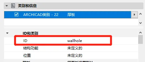
(The image above shows where to set the “Board ID”.)
Next, select the irregular window, then open View > 3D View Options > 3D Projection Settings. In the dialog box, select Parallel Projection. For the Custom Axis, choose Top View. Leave the other settings unchanged and click OK.
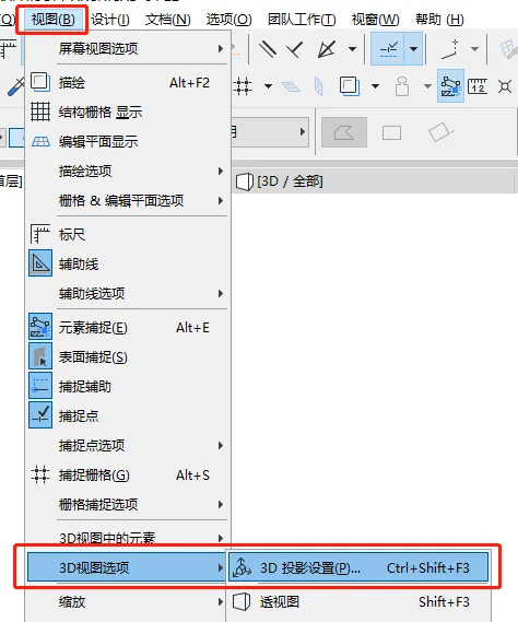
(The image above shows the perspective view settings.)
Finally, select the irregular window and save it by navigating to File > Gallery and Objects > Save Selection As > Window. In the “Save as Door/Window” dialog that appears, choose the horizontal plane and click Continue Save.
In the following “Save Window” dialog, enter a name for the custom window and click Save. When the “Modify Basic Settings of Objects” dialog appears, click OK to complete the process.
(The image above shows the “Save as Door/Window” dialog.)
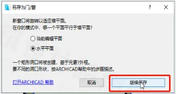
(Another view of the “Save as Door/Window” dialog.)
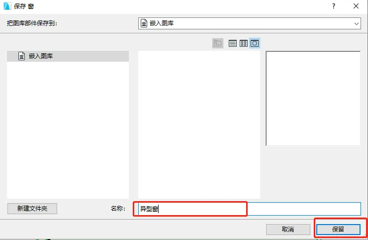
(The “Save Window” dialog box.)
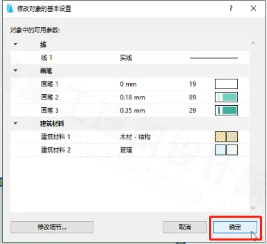
(The “Modify Basic Settings of Objects” dialog box.)
Finally, open the window tool, locate your custom window, and place it onto the wall.
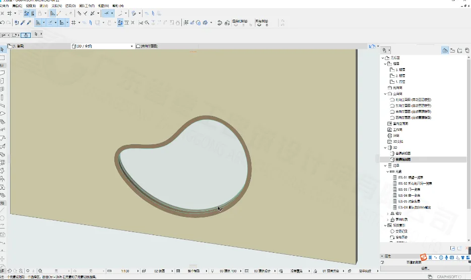
(The final result is shown in the image above.)


Must log in before commenting!
Sign Up