Source: Fancheng BIM
AECOsim Building Designer CONNECT Edition (ABD) is a Bentley software product tailored for the construction industry. It supports modeling of building structures, ducts, pipelines, and electrical systems. In the latest update, ABD has been renamed OpenBuildings Designer Connect Edition (OBD) to align with Bentley’s Open series software. So, if you come across the name OBD, don’t be surprised—it’s essentially the same software with a new name.
Pipeline clash detection has always been a crucial part of building projects. Below, we’ll guide you through the process of setting pipeline styles and types before drawing pipelines in ABD.
Follow these steps to set up pipelines in ABD:
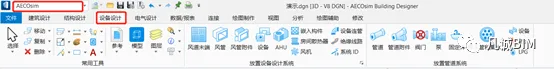
1. Launch the software and switch to the AECOsim workflow. In the panel, click on “Device Design”. Here, you’ll find commands for working with pipes, ducts, accessories, and devices.
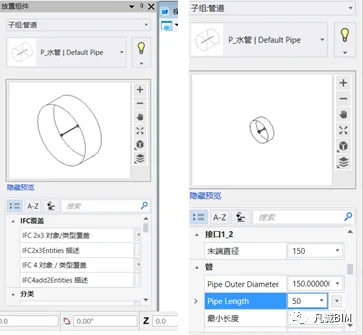
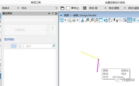
2. When you click the pipeline command, a property panel will open with options for drawing pipelines. Here, you can adjust basic settings such as pipe diameter, slope, and foundation offset.
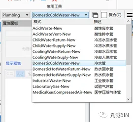
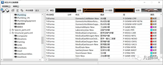
3. Before drawing, select the appropriate category style by choosing the system that corresponds to your pipeline.
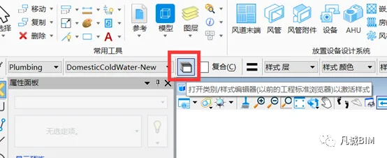
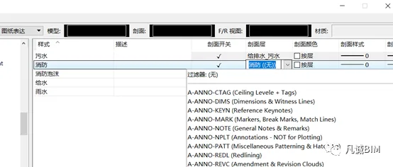
If no default pipeline matches your requirements, you can edit the category style. Click the small white box next to the category style to open the category style editor, where you can create new categories and styles.
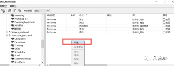
4. To create a new style, select a category from the right-hand panel, right-click, and choose New.
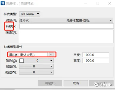
5. In the dialog box that appears for creating a new style, enter the style’s name and assign it to a layer. It’s recommended to create a new layer for this style and set its color to By Layer. This allows you to control the style’s color through the layer settings.
6. In the style editor, select the expressions highlighted in red and assign their layers and colors accordingly.
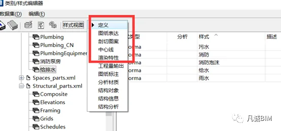
Once you complete these settings, you’ll be ready to draw pipelines.


Must log in before commenting!
Sign Up