This highway engineering project is located in the northwest area of a certain county, within the county’s planned development zone. It is one of the key infrastructure projects during the 13th Five-Year Plan period. The design scope includes highway centerline alignment, standard cross-section for the roadbed, route plane and longitudinal profiles, as well as bridge structure design. The project spans a total length of 180.55 km, with a design speed of 120 km/h, a roadbed width of 30 meters, six lanes in each direction, and a bridge and culvert load classification of Highway I. The construction period is planned for 26 months, with a total investment of 11.255 billion yuan.
Key Features of the Highway Engineering Design
This project presents significant design challenges due to its terrain and scope. It primarily involves road engineering, culvert engineering, and bridge engineering. During the design phase, it is essential to comprehensively consider factors such as topography, natural environment, and hydrology to develop an integrated information data system. After compiling all relevant data, the information is visualized using simulation images. This process demands extensive data collection, organization, and advanced modeling techniques.
The structures involved in this project are illustrated in 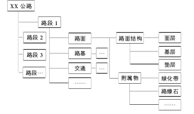
Figure 1: Structures Covered in the Highway Engineering Project
Due to the complexity of integrating various processes in BIM technology modeling—especially during the imaging stage—significant time and effort are required. In cases where data is incomplete or inaccurate, adjustments must be made promptly based on actual monitoring results until a scientifically sound design is achieved. When using BIM technology for modeling, it is crucial not only to represent the main project components but also to focus on preparatory work, construction materials, and mechanical equipment during the early stages.
Application of BIM Technology in the Highway Engineering Design Phase
1.1 Preliminary Preparation Stage
The preliminary preparation for this engineering project includes two main phases: feasibility study and design. The design phase itself consists of preliminary design and construction drawing design, each with distinct workflows and BIM application approaches. BIM visualization enables early detection of design omissions, while the collaborative and optimized use of BIM greatly reduces workload during this initial stage.
Traditional design methods rely on contour line interpretation and on-site data, which do not provide an intuitive understanding of terrain, landforms, or land status. This places higher demands on designers’ expertise. BIM technology facilitates the clear identification of terrain and landforms within the project area and significantly enhances the quality and efficiency of construction. Terrain model data created with BIM typically includes formats such as DLG, LAS, DEM, and TIFF, which form the basis for design work. Due to varying data sources, coordinate systems may differ; BIM technology integrates these into a unified database to meet the needs of diverse stakeholders.
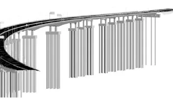
Figure 2: Simulated Assembly Effect Diagram
1.2 Highway Centerline Design
The highway centerline design is the most critical part of this project and is influenced by numerous factors. During the design process, it is important to analyze these factors thoroughly. BIM technology allows for simulation of the highway centerline, helping identify potential issues, develop targeted solutions, and continuously refine the design. This approach also fosters the advancement of BIM applications in highway engineering design.
1.3 Standard Cross-Section Design of the Roadbed
This project introduces a new cross-sectional design method—assembly—using BIM technology during the roadbed standard cross-section design stage. The simulated assembly effect is illustrated in Figure 2. This standard cross-section is programmed and customized via an editor, allowing designers to embed the design concepts for the entire project directly into the model. Consequently, designers avoid manually revising common issues across cross-sections.
BIM technology assigns codes to standard cross-sections and enables attribute editing, including engineering styles and materials. It also produces a comprehensive 3D rendering accessible to all project participants, improving communication and understanding.
1.4 Route Plan and Vertical Profile Design
Traditional route planning methods often use simple intersection techniques. BIM technology, however, offers multiple routing options, enabling designers to create shortcuts and complete design tasks more efficiently. For complex curve types—such as S-shaped curves, egg-shaped curves, and other special alignments—custom designs can be tailored to designers’ preferences to meet drawing requirements.
Once the route is created, the vertical profile is adjusted using two methods: geometric shaping and panoramic layout. This ensures consistency between the vertical profile design and the route plan.
1.5 Road Model Generation
After completing the design of the roadbed’s standard cross-section and the route’s longitudinal profile, specific criteria must be set—for example, bridge cross-sections and slope widening. Material labels are assigned to point codes and connection codes in the road model to facilitate rapid analysis. Civil3D is then used to generate boundary lines for judgment conditions and create the road model. Designers subsequently generate road surfaces based on this model.
1.6 BIM Technology 3D Visualization Platform
Following road model creation, to provide all project personnel with an intuitive understanding of the road’s design and the project’s actual status, the BIM-generated data is imported into the Infraworks platform. Using a custom coordinate system, field measurement data is integrated to produce a 3D digital image model. This model includes additional structures such as roadbeds, pavements, and guardrails, and is further refined for reporting purposes.
The BIM 3D visualization platform furnishes realistic experiences for construction teams, enabling them to evaluate the design’s reasonableness and offer informed feedback and suggestions.
1.7 Bridge Structure Design
Bridge design is also accomplished using BIM technology. It covers the design of upper and lower bridge structures such as hollow slabs, T-beams, guardrails, bridge piers, cover beams, and more, creating a family library of components. By assembling and modifying these families to meet design requirements, designers can greatly enhance their efficiency. This approach also helps other personnel promptly detect any conflicts in the construction of bridge structural steel and identify design shortcomings.
Source: China High Tech Technology, Issue 15, 2021
Author: Wen/Huo Xuemi
For learning and exchange purposes only. Copyright belongs to the magazine and the original author. For any infringement concerns, please contact us for removal.


Must log in before commenting!
Sign Up