Article source: Revit Bicycle
In Revit, a filter is a collection that allows you to isolate multiple elements based on specific criteria. Filters are an essential feature in Revit, playing a role as important as CAD layer systems for organizing and managing your model. Here’s how to set up filters:
1 & 2. Name the filter—use a simple and clear name;
3. Choose a category to specify which elements the filter applies to;
4. Define the filtering criteria, so the filter extracts all elements within the chosen category that meet those conditions.
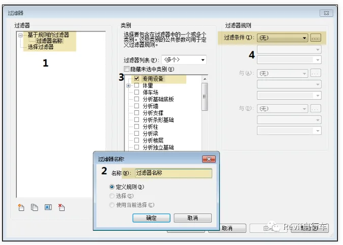
(Figure 1)
At this stage, you might wonder if there’s a more convenient way to add filters. Let’s explore whether Dynamo offers any automation for this task. In this example project, the parameter “concrete strength grade” has been added to concrete elements.
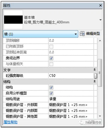
(Figure 2)
Step One:
First, use the ‘ParameterFilterElement.ByRules’ node in Dynamo to create a filter. This node requires three inputs in order: ‘filter name,’ ‘category,’ and ‘filter rules’ (corresponding to points 1, 3, and 4 in Figure 1).
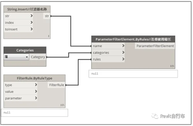
(Figure 3)
Step Two:
Next, specify the filter name. This step only requires a string input that defines the name, as shown in points 1 and 2 of Figure 1.
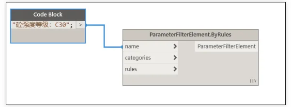
(Figure 4)
Using this method alone is slower than setting filters directly in Revit. Since we want to add filtering conditions based on concrete strength grades, a good approach is to use a ‘CodeBlock’ in Dynamo to generate a sequence of increasing numbers. Then, combine these numbers with the prefix “concrete strength grade C” to create the desired filter names.
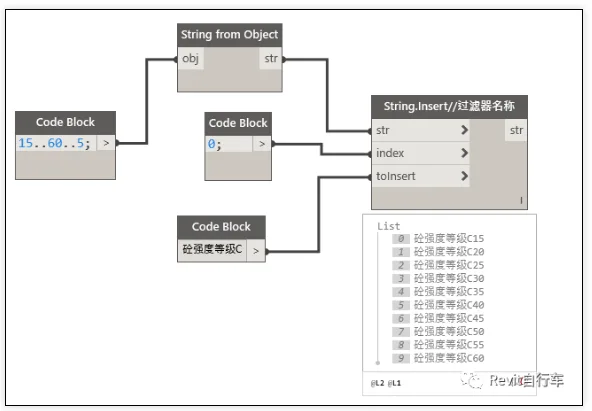
(Figure 5)
Similarly, each filter name corresponds to a filter condition value. By adding the prefix “C” before the number, you can generate both the ‘filter name’ and ‘filter condition value’ sets, as illustrated below.
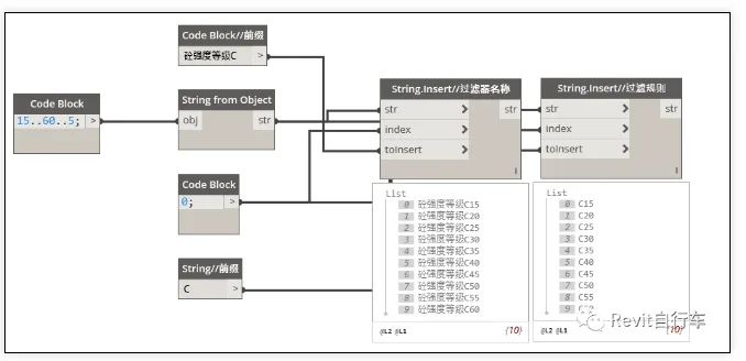
(Figure 6)
Note: For parameter values that do not follow a linear or predictable sequence, other Dynamo nodes can be used to extract existing element properties directly from the model.
Step Three:
Now, use the ‘FilterRule.ByRuleType’ node to define the filter criteria. This node reads the parameter properties of the selected category and creates filter rules based on property values and comparison operators.
For example, as shown below, the node reads the ‘concrete strength grade’ parameter of ‘wall’ elements, compares it with the connected value, and applies the filter using the selected comparison type (such as ‘includes’).
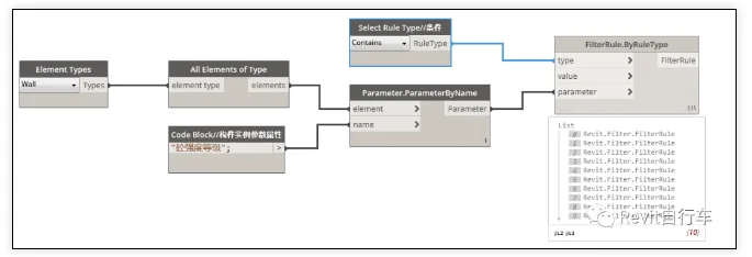
(Figure 7)
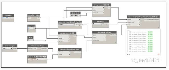
Final Step:
The expected outcome is shown below: a filter list with the corresponding filter names, selected component categories, and properly set conditions that match the requirements.
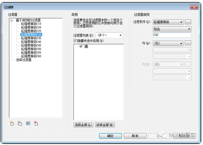
(Figure 8)
By connecting all the above nodes in series, you achieve the following result.


Must log in before commenting!
Sign Up