The Binjiang Building project is situated in the bonded zone of Z City, J Province, within Zhangjiagang City. Covering an area of approximately 50,000 square meters, this construction site lies in northern China, on a plain with favorable geological conditions. Overall, it meets the standards of conventional construction projects.
The client requires two office towers aligned east-west, connected by a three-story podium foundation. Both the west Tower A and east Tower S rise 31 stories, reaching a height of 140 meters. The podium consists of three buildings—Podium A, Podium B, and Podium C—each three stories tall, with a building height of 20.2 meters. The basement serves as a parking garage and equipment room, spanning roughly 30,000 square meters.
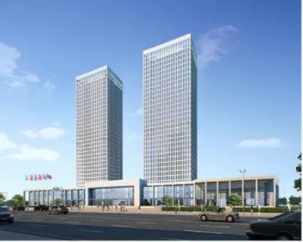
Figure 1: Engineering Rendering
BIM Collaborative Management Analysis
Technical Quality
In technical quality management, BIM serves primarily as a management tool to enhance collaboration by assigning clear responsibilities at every stage through tailored management plans. This is especially crucial during the design, construction, and material supply phases, where strict accountability is enforced to ensure individual responsibility. This approach facilitates efficient data collection and communication.
Regular meetings are held for discussion and reporting, accompanied by monitoring of various indicators to guarantee effective project collaboration and synergy.
Using three-dimensional visual inspections, drawings can be reviewed from any angle or section through the 3D model. During the modeling process, discrepancies were discovered between flat drawings and centralized annotations. Once identified, the design institute promptly made corrections to improve review efficiency.
Post-model creation, 3D visualization revealed structural issues such as misaligned columns between floors, stair columns not aligned with walls, and stair columns overlapping with door positions, indicating the need for design revisions.
Construction planning for the podium’s post-pouring scaffolding was simulated. The plan requires that formwork and its supporting systems be single-support and disassemblable, avoiding integration with the indoor full frame. By creating a 3D construction model of this post-pouring strip via BIM, the construction site could be simulated accurately, and materials such as steel pipes, fasteners, and templates could be precisely accounted for, as illustrated in Figure 2.
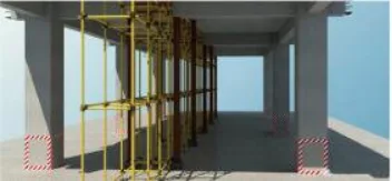
Figure 2: Scaffold Construction Plan Simulation
Automatic identification of high formwork areas was performed using LubanTransRevit, importing building models into Luban civil engineering software for quick localization of high formwork components. Six high formwork zones were identified in the skirt section, many requiring beam components with high formwork support systems. To verify accuracy, project personnel manually cross-checked drawings, confirming the software’s results perfectly matched, as shown in Figure 3.
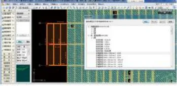
Figure 3: Automated Detection of High-Support Formwork Areas
For controlling net height, Company D adopted collision detection within the BIM information management system, achieving effective height verification results, as depicted in Figure 4.
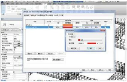
Figure 4: Warning Area Search Settings
Steel bar cutting and processing are labor-intensive and time-consuming. This project utilized Luban cutting by importing BIM models, automatically generating steel bar material lists and significantly improving steel bar layout efficiency.
Pipeline design is particularly complex during the project’s design phase. Historically, pipeline layouts often require multiple modifications, impacting project quality and complicating maintenance and quality control in later stages. By leveraging BIM for pipeline design and conducting collision tests, many such problems can be avoided.
Figure 5 shows the comprehensive layout section of computer room pipelines, demonstrating the absence of traditional schematic diagrams.
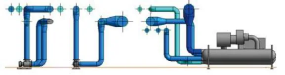
Figure 5: Comprehensive Layout of Computer Room Pipelines
Pipeline quality can be visualized in 3D, with collision tests and virtual simulations used to better evaluate and optimize designs. Additionally, establishing reasonable allowances for changes helps prevent quality issues during actual construction.
For drawing refinement, the 3D environment allows viewing any model position from multiple angles. Unreasonable areas can be identified and addressed by deepening the 3D model, enabling comparative analysis of various solutions and selecting the optimal one. This is especially useful for complex computer rooms with dense pipeline layouts and numerous equipment. RevitMep software facilitates this deepening process and can directly output construction drawings, thereby improving construction efficiency, as shown in Figure 6.
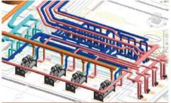
Figure 6: Deepening Effect on Computer Room Pipelines
After pipeline synthesis and optimization using RevitMep, the 3D model is imported into Navisworks for collision detection. Identified collisions are addressed through continuous modification, ensuring pipeline design accuracy and allowing room for adjustments during construction. This approach supports future maintenance and produces more focused sectional views, making design drawings clearer, as illustrated in Figure 7.
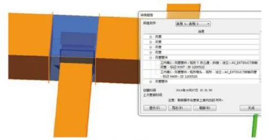
Figure 7: Collision Detection Diagram
Cost Control
Traditional quantity calculation in construction relies heavily on manual measurements and statistics derived from drawings or CAD files. In many small to medium-sized enterprises or construction projects, primitive methods based on CAD drawings and cost calculation software are common. These approaches often struggle with preliminary data collection, require significant manpower, and are prone to errors. Manual calculations are time-consuming and often fail to meet strict project timelines, posing a critical challenge.
To overcome this, advanced BIM building information management is adopted, leveraging extensive early-stage data collection combined with streamlined operations to produce accurate quantity calculations. Figure 8 illustrates how collaborative management mechanisms and BIM assist in effective cost tracking.
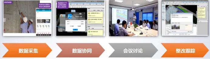
Figure 8: Cost Tracking Chart
With rapid economic growth and intensifying competition, refined management becomes essential. Many construction enterprises still use rough management methods, leading to quality issues and inefficiencies. Implementing BIM and advanced management techniques enables better project management, increased efficiency, and reduced problems related to materials and costs.
Liu Yu (Dalian University of Technology)
For learning and communication purposes only. Copyright belongs to the original author. If any infringement occurs, please contact us for removal.


Must log in before commenting!
Sign Up