The steel reinforcement capabilities that come with Revit are quite limited. Even in building structures where Revit generally performs well, its steel reinforcement tools often fall short. This is especially true for irregular structures, where accurately modeling steel reinforcement can be nearly impossible.
Here, I propose a method to use Revit for adding steel bars to bridges. Bridges often feature many irregular structures, and the steel bar designs for them usually lack consistent rules. To make matters more complicated, different design institutes apply varying standards for bridge steel bars.
The approach for adding steel bars to bridges can be summarized as follows:
1. For structures with defined rules:
1) Create a model line family representing the reinforcing steel bars;
2) Use Dynamo to place these steel bar model lines in their corresponding locations;
3) Use a custom-developed plugin to convert the model line family into actual steel bars, including longitudinal bars, stirrups, and arbitrary bars.
The plugin demonstration can be found in the video: __AI_S_TURL_0__
A relatively complete project example is also available here: __AI_S_TURL_0__
Additionally, there is a method for generating full bridge steel bars based on CAD standard drawings. This process strictly follows the drawing dimensions and includes a complete modeling workflow, with an example at: __AI_SBT-URL-0__
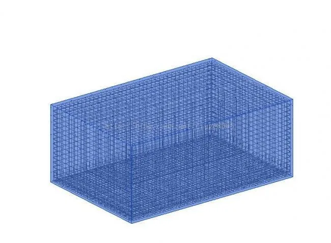
2. For distributed steel bars:
1) Use Dynamo to generate steel bar model lines;
2) Convert these model lines into steel bars.
For the plugin, see the videos below:
http://v.youku.com/v_show/id_XMTg1NjI2NTkwMA==.html?spm=a2hzp.8253869.0.0
http://v.youku.com/v_show/id_XMTg1NzMwMjI2NA==.html?spm=a2hzp.8253869.0.0
http://v.youku.com/v_show/id_XMTg1ODQ3NjIzNg==.html?spm=a2hzp.8253869.0.0
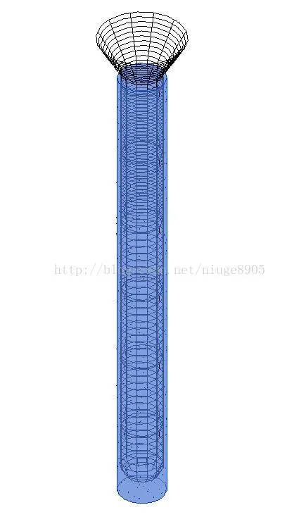
3. For structures with clear, well-defined rules (such as piles and abutments):
Simply write the reinforcement rules into a program and generate the steel bars with a single click.


Must log in before commenting!
Sign Up