When working with Revit to create drawings, it is common to encounter inconsistencies in the elevation levels of a project’s basement. When annotating mechanical and electrical pipelines, it’s essential to label them according to the basement ground elevation. However, since the basement ground elevation cannot be standardized, you need to manually select specific areas and generate elevation thumbnails to indicate these elevations accurately.
This article shares a quick method for creating these elevation thumbnails by utilizing floor slabs within civil engineering models.
Steps to implement:
- Extract all contours of the basement building surface layer, filter out the boundary lines of this layer, and then generate detailed drawing lines based on those boundary lines.
- Create a new elevation marker family for standard annotations and assign the basement surface elevation to this annotation family.
Below is the complete code for this process:
public Result Execute(ExternalCommandData commandData, ref string message, ElementSet elements)
{
 UIApplication uiApp = commandData.Application;
 UIDocument uiDoc = uiApp.ActiveUIDocument;
 Document doc = uiDoc.Document;
 Selection sel = uiDoc.Selection;

 try {
  Transaction trans = new Transaction(doc);
  trans.Start("Draw Detail Lines");
  FilteredElementCollector col = new FilteredElementCollector(uiDoc.Document);
  col.OfClass(typeof(FamilySymbol)).OfCategory(BuiltInCategory.OST_GenericAnnotation);
  FamilySymbol familySymbol = col.FirstElement() as FamilySymbol;
  FilteredElementCollector collector = new FilteredElementCollector(doc);
  ICollection<Element> floorcol = collector.OfClass(typeof(Floor)).ToElements();

  foreach (Element elem in floorcol) {
   Floor floor = elem as Floor;
   if (floor.Name.Contains("楼板"))
   {
    Level level = doc.GetElement(floor.LevelId) as Level;
    if (level.Name.Contains("B1") && level.Name.Contains("ST"))
    {
     // Get the floor's relative elevation offset
     double offset = floor.LookupParameter("自标高的高度偏移").AsDouble();
     double levelHeigh = (level.Elevation + offset) * 304.8 / 1000;
     string levelParam = levelHeigh.ToString("0.000");
     XYZ point = (floor.get_BoundingBox(doc.ActiveView).Max + floor.get_BoundingBox(doc.ActiveView).Min) / 2;

     FamilyInstance instance = doc.Create.NewFamilyInstance(point, familySymbol, doc.ActiveView);
     Parameter parm = instance.LookupParameter("标高1");
     parm.Set(levelParam);

     GeometryElement geometry = floor.get_Geometry(new Options());
     foreach (GeometryObject geomObj in geometry) // Retrieve edges and faces of geometry
     {
      Solid geomSolid = geomObj as Solid;
      if (null != geomSolid)
      {
       foreach (Face geoFace in geomSolid.Faces)
       {
        if (geoFace is PlanarFace) {
         PlanarFace plFace = geoFace as PlanarFace;

         // Identify the floor surface
         if (plFace.FaceNormal.Z == 1)
         {
          EdgeArray array = plFace.EdgeLoops.get_Item(0);
          foreach (Edge ed in array)
          {
           Curve curve = ed.AsCurve();
           doc.Create.NewDetailCurve(doc.ActiveView, curve);
          }
         }
        }
       }
      }
     }
    }
   }
  }
  trans.Commit();
 }
 catch (Autodesk.Revit.Exceptions.OperationCanceledException e) {
  return Result.Cancelled;
 }
 catch (Exception ex) {
  TaskDialog.Show("Revit", ex.Source + "n" + ex.Message + "n");
  return Result.Failed;
 }
 return Result.Succeeded;
}
The actual output looks like this:
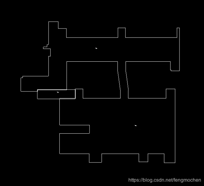
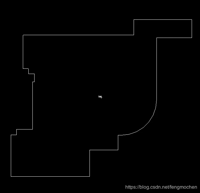
This method offers a straightforward approach to generating thumbnails. However, it requires the floor slab modeling to be accurate and complete. If the civil model’s floor slabs are incomplete or overlapping, you may need to manually capture and adjust the thumbnails accordingly.


Must log in before commenting!
Sign Up