1. Project Introduction
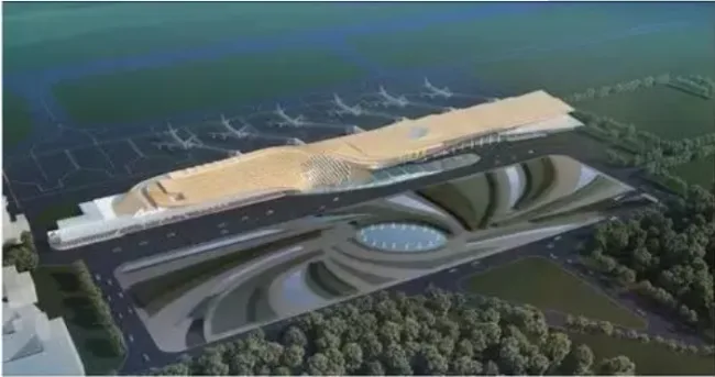
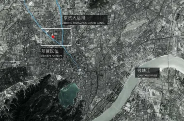
This project involves the renovation and expansion of Tongren Airport Terminal. It covers a planned construction land area of 58,000 square meters, with a total building area of 11,887.35 square meters and a height of 19.9 meters. The terminal has two floors above ground and is designed for a service life of 50 years. Inspired by local Buddhist culture, the design adopts the theme of phoenix reincarnation. Using dual-track sweeping and curved flipping techniques, the overall shape of the airport resembles a Buddhist conch shell, symbolizing the phoenix’s rebirth and eternal life. When viewed from above, it resembles the auspicious phoenix bird—the peacock. The metal aluminum panels on the terminal’s surface vary in shape, expanding and contracting like the colorful wings of a peacock shining under the sunlight.
2. Background of BIM Technology Application
The project faced several key challenges:
- How to effectively translate the architect’s conceptual design into practical construction plans.
- Managing complex irregular surfaces, each with varying normals at different points. After installing the curtain wall, ensuring the spacing and gaps between panels meet waterproofing and other functional requirements, while preserving the designer’s intended aesthetic without deformation or distortion.
- A tight project schedule. Traditional on-site methods for locating curtain wall installation positions require waiting until the structural framework is complete and involve extensive positioning data and repeated calculations.
- Curved surfaces necessitate curtain wall panels of varying sizes. Conventional on-site cutting and installation methods cannot meet the timeline and risk accumulating construction errors.
To address these challenges, the team turned to BIM technology with the goals of:
- Obtaining curtain wall positioning information earlier in the process to ensure construction timelines.
- Providing accurate prefabrication data for curtain wall panels, enabling early processing and minimizing on-site errors.
- Optimizing curtain wall arrangements to ensure the original design intent is realized while controlling costs.
3. Introduction to BIM Application
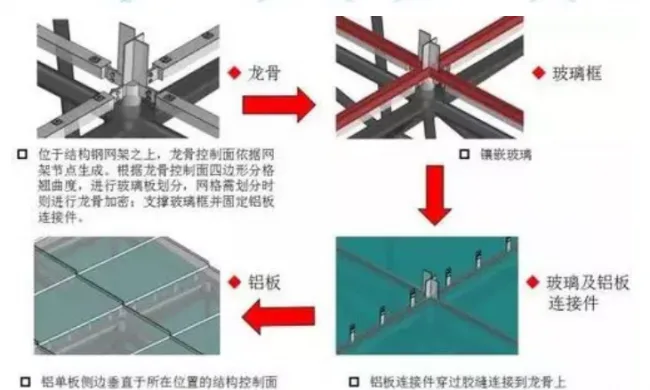
The curtain wall installation is based on a structural grid. The first step was to accurately reconstruct the structural grid model using BIM technology, enabling precise digital data for each structural node.
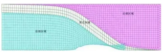
Grid Plan
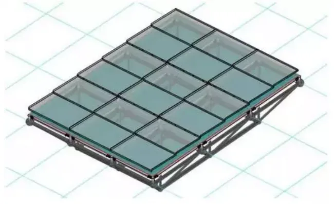
With the structural model established, Grasshopper’s data control functionality was used to initially arrange fixed-size curtain wall panels. This ensured that the panel anchor points aligned properly with the normals at structural nodes. However, after this initial layout, most panel corners had four non-coplanar points. The distance from any one of these points to the plane formed by the other three indicates the curvature at that point. Excessive curvature could negatively impact design performance and complicate construction.
To resolve this, a secondary optimization of the curtain wall divisions was performed. By rewriting the Grasshopper source code, a global search identified locations with high warp values. Analyzing this data helped pinpoint improperly divided curtain wall areas, which were then optimized. Non-standard units were replaced with standard ones where possible, and panel size, type, and quantity were rationalized to reduce design and construction complexity, saving costs and enhancing quality.
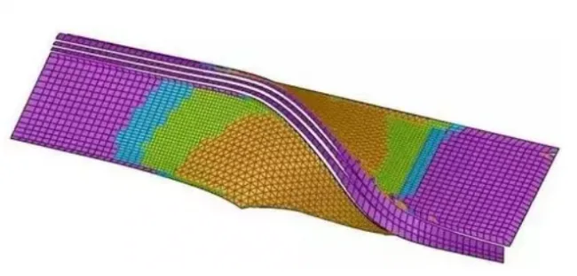
Curtain Wall Partition Effect
Following optimization and node division, construction process modeling and simulation were conducted to accurately recreate the actual installation components. This provided a reliable basis for calculating curtain wall panel positioning, prefabrication dimensions, keel lengths, and other details, facilitating efficient prefabrication and installation.
Regarding curtain wall connections and detailed construction, aluminum veneer connections were optimized. When arranging the aluminum veneers, their sides were set perpendicular to the structural control surface at each position. The corner points of the veneers aligned with keel intersections, and the edges matched keel directions. This ensured connecting pieces could smoothly pass through adhesive joints and connect securely to the keel, simplifying the assembly between veneers and keels.
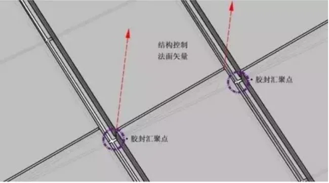
Schematic Diagram of Aluminum Veneer and Adhesive Joint Correspondence
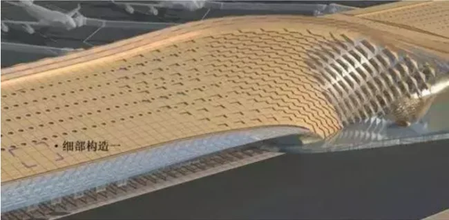
Detailed Structure of Roof Curtain Wall
4. BIM Application Results
During the design phase, BIM technology was used to create a 3D model, enabling early detection of design issues as the model developed. BIM’s visualization capabilities facilitated communication among all project stakeholders and allowed real-time adjustments to the assembly model, significantly improving the efficiency of the assembly structure design.
In the construction phase, especially for complex irregular surfaces, BIM technology enabled simulation of complex curved components prior to actual construction. This allowed detailed handling of special nodes and helped avoid potential issues related to layout and installation on-site.
Article source: BIM website


Must log in before commenting!
Sign Up