In prefabricated shear wall building systems, vertical prefabricated components (shear walls) are connected using sleeve grouting. The vertical reserved steel bars within the cast-in-place layer, which serves as the transition between cast-in-place and prefabricated construction, are installed using post-inserted steel bar technology.
The process begins by fabricating positioning hoops and positioning steel plates based on the locations of the reserved steel reinforcements on the wall. These components are used to accurately position and secure the reserved steel bars that will be inserted later. Precise positioning of these rear-inserted vertical steel bars is critical, as it significantly reduces the need for adjustments after concrete pouring and ensures the correct installation of the vertical prefabricated components.
Technical Process
1. Construction Process Flow
Design detailing → Fabrication of positioning steel plates and hoops → Construction of the transfer floor formwork → Layout of wall positioning control lines → Binding of floor reinforcement → Installation of positioning hoops and steel plates → Insertion of vertical reserved steel bars → Concrete pouring of the floor.
2. Key Operational Points
(1) Design Detailing
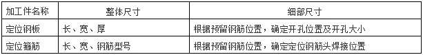
Based on the dimensions of the prefabricated wall components, detailed designs are prepared for the positioning steel plates, positioning hoops, and the length of the post-inserted steel bars. Processing drawings are created to guide fabrication. Table 1 below outlines the size requirements for positioning steel plates and hoops. The reserved steel bars must be cut to the specified anchorage length according to design.
Table 1: Design Dimensions of Positioning Steel Plates and Hoops
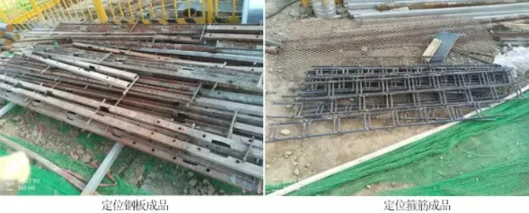
(2) Fabrication of Positioning Steel Plates and Hoops
Follow the detailed processing drawings strictly to fabricate the positioning steel plates and hoops. The finished products should conform precisely to the specified dimensions, as shown below.
(3) Construction of Transfer Floor Slab Formwork
After completing the reinforcement binding for the cast-in-place walls and beams, proceed with the formwork construction. Once complete, conduct formwork acceptance inspections.
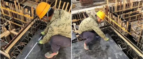
▲ Wall positioning control line layout
(4) Wall Positioning Control Line Layout
Once the cast-in-place floor slab formwork is installed, mark the wall positioning control lines clearly on the formwork. Use a visible white ink that is resistant to erasure. These control lines serve as crucial reference points for installing positioning clamps and steel plates.
(5) Floor Slab Reinforcement Binding
After the layout, bind the reinforcement for the cast-in-place floor slab. Protect the control lines carefully during this process to prevent damage or erasure.
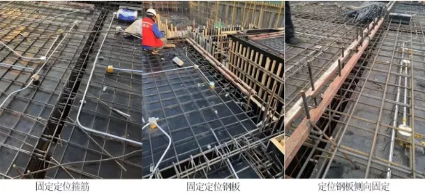
(6) Installation of Positioning Hoops and Steel Plates
Once the bottom reinforcement of the floor slab is tied, attach the positioning hoops along the wall control lines. The hoops should be tied to the bottom reinforcement and secured with spot welding at intervals.
After completing the upper reinforcement, install the positioning steel plates according to the control lines. Ensure the holes in the steel plates align perfectly with the gaps in the positioning hoops. The steel plates should be positioned so their bottom surface is 5 cm above the concrete pouring surface.
Connecting steel bars are then welded on both sides of the positioning plate to the bottom floor reinforcement. One end of these bars is welded to the steel plate, and the other end is fixed firmly to the floor reinforcement and formwork.
(7) Insertion of Vertical Reserved Steel Bars
Insert the reserved steel bars through the openings in the steel plate reinforcement. The insertion length into the cast-in-place wall must comply with the design’s anchorage requirements. Tie and connect the inserted bars with the longitudinal bars of both the prefabricated and cast-in-place layers, securing them with the positioning hoops.
Spot welding of the inserted longitudinal bars to other steel bars is strictly prohibited. After completing the insertion and connection of the reserved reinforcement, close the formwork for the cast-in-place wall.
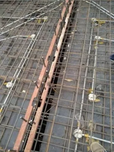
▲ Insertion of reserved longitudinal bars
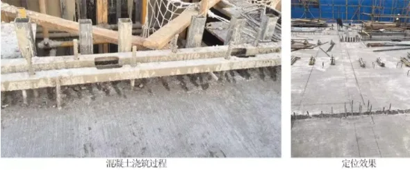
(8) Floor Concrete Pouring
After reinforcement binding is complete and accepted, proceed with pouring the floor concrete. During pouring, insert the vibrating rod through the reserved holes in the steel positioning plates to minimize direct contact with the plates and reduce displacement of the reserved anchoring steel bars.
The positioning steel plates should only be removed after the concrete has fully cured and the next construction phase can commence.
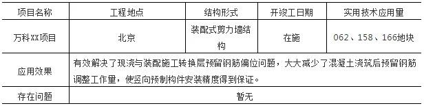
Application Examples


Must log in before commenting!
Sign Up