This article summarizes 25 common construction quality issues encountered in prefabricated buildings and offers prevention strategies. Many of these problems arise during the construction process. By sharing prevention measures and lessons learned, we aim to help professionals avoid similar issues in future projects.
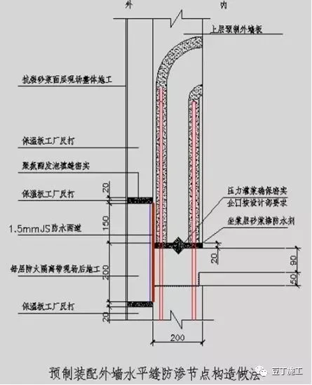
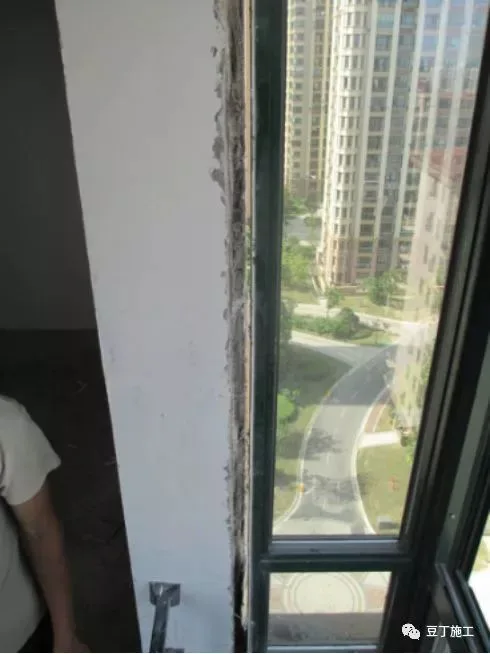
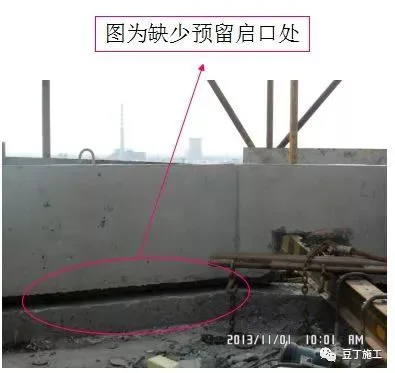
1. Exterior wall panels on some components were not designed with a 600mm upward flip or a water stop groove, leading to exterior wall leakage.
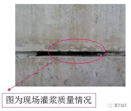
1.1 The horizontal joint between components is 20mm wide, and insulation board joints were filled directly with cement mortar. This created an indirect water tank on the exterior wall without any water stop measures, causing leakage.
Prevention measures for this issue include:
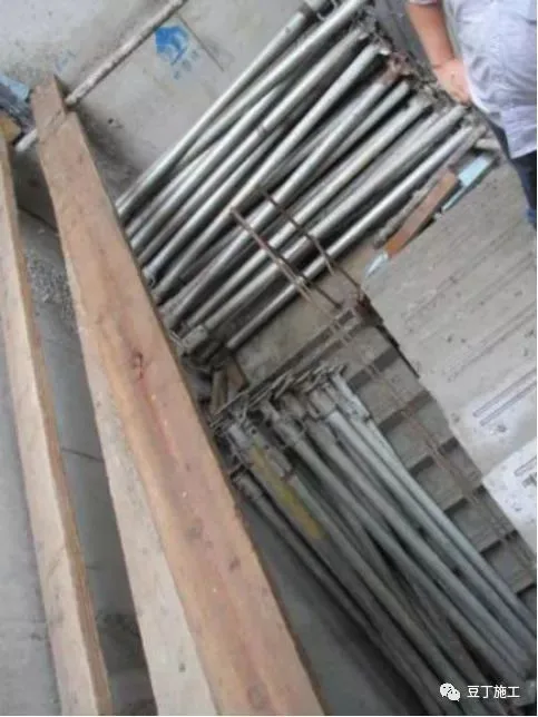
- The design department must strictly adhere to the Technical Specification for Prefabricated and Assembled Integrated Shear Wall Structure System (DGJ32/TJ125-2011) when modifying components. For example, Qikou waterproofing is applied to buildings numbered 96 and above in Haimen Century City, as well as buildings 5 and 8 in Shenyang Century City. See the image below:
- Treatment of floors without water stop openings involves:
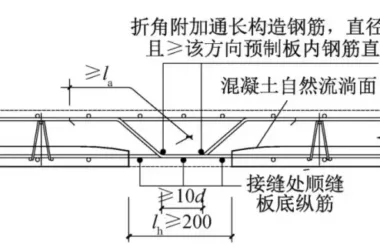
① Cutting and chiseling the insulation board reversed at the bottom of the upper prefabricated wall panel and the top of the lower exterior wall panel as per node drawing requirements. One side serves as a construction fire isolation zone, while the other facilitates waterproofing.
② Before installing the upper wall panels, clean the wall base thoroughly. After internal and external grouting, install, calibrate, and temporarily fix the panels. Spray water into grouting holes before grouting to ensure proper material flow and compaction.
③ Apply two coats of JS cement-based waterproof coating over a 200mm width above and below the horizontal joint.
④ Conduct a spray test similar to that for exterior aluminum windows. If no leaks are detected, proceed with external insulation construction.
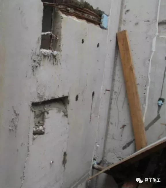
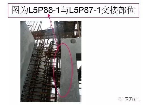
2. At the L-shaped handover position (hidden column), reinforcement processing on one side of the wall panel was not properly chiseled for overlapping, and components on both sides had already been fixed, creating a structural safety hazard.
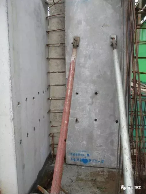
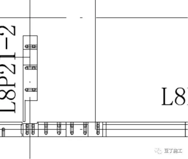
Prevention measures:
- Organize technical personnel to thoroughly study the Technical Specification for Prefabricated and Assembled Integral Shear Wall Structure System (DGJ32/TJ125-2011) and accumulate practical experience.
- Technicians must prepare detailed plans and technical briefings.
- Component factory acceptance must strictly follow component drawings and acceptance criteria.
- On-site component reception requires inspection against component diagrams.
- Technicians should carefully review critical cast-in-place nodes after hoisting and positioning.
- Quality officers must inspect steel bar connections at node locations.
- The project department must implement a “three inspection system” for quality control.
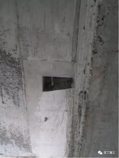
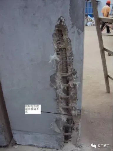
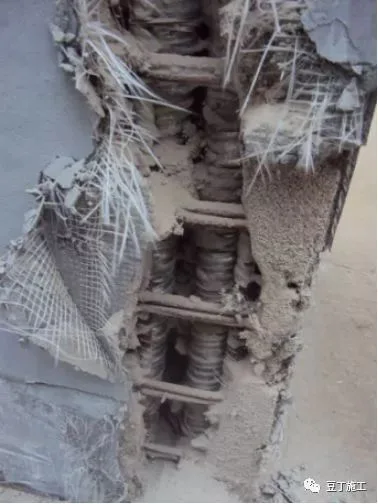
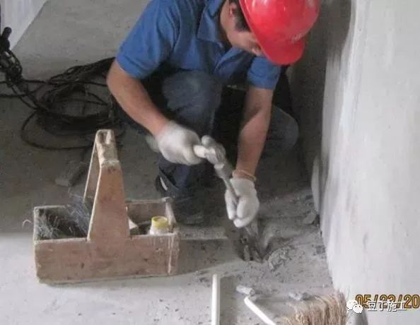
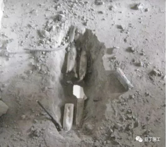
3. Insufficient concrete pouring in reinforced cast-in-place node areas of edge components poses a quality risk. Conventional handling and prevention methods apply.
3.1 Cast-in-place nodes are not fully compacted and contain voids (“dog holes”), compromising structural safety. Conventional treatment methods apply.
4. Failure to weld steel plates between non-load-bearing walls promptly can cause cracks. Project personnel must address this seriously.
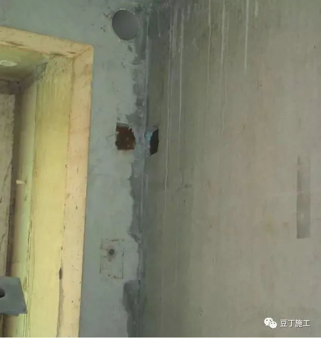
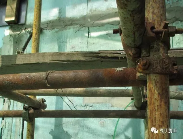
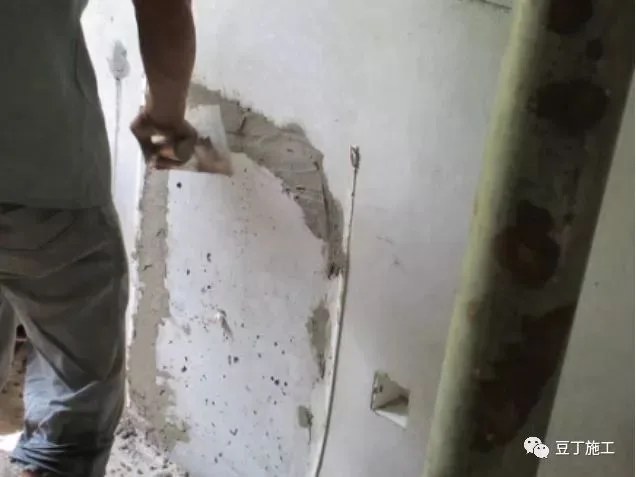
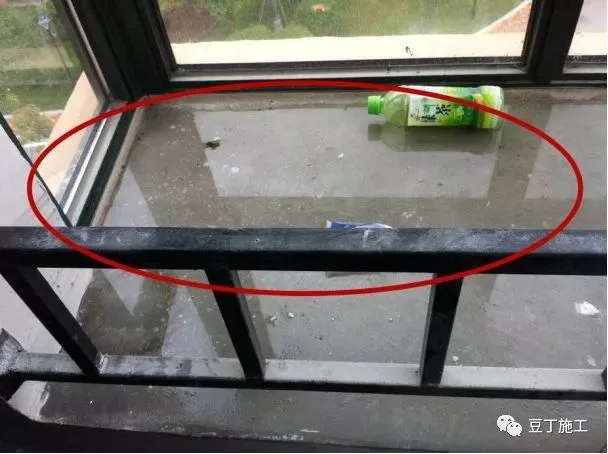
5. Improper installation of suspended scaffolding and inadequate treatment of conduit joints have led to leakage.
5.1 Improper sealing of scaffold and screw holes can result in leakage.

During component processing, concrete around corrugated pipes and wire box locations was not compacted properly, resulting in exterior wall leakage.
5.3 Leakage occurs at the location of the online box and conduit.
5.4 The processing plant did not follow drawings and installed the insulation board up to the bay window edge, causing leakage.
Prevention measures:
- Design department: Coordinate with construction on cantilever frame placement to avoid conflicts with longitudinal steel bars during design conversion.
- Processing plant: Follow component diagrams and instructions strictly. Quality officers must monitor every process.
- Control concrete slump, sand and gravel grading, vibration, and curing, especially around corrugated pipes and wire box concentrations.
- On site: Develop a detailed sealing plan for cantilever holes, pipe joints, and screw holes. Clean and moisten areas before sealing. Use dry, hard cement mortar with micro-expansion agents applied in layers. Seal cantilever holes to wall thickness, then apply two coats of JS cement-based waterproof coating after drying. Quality officers should conduct thorough inspections of each facade and floor.
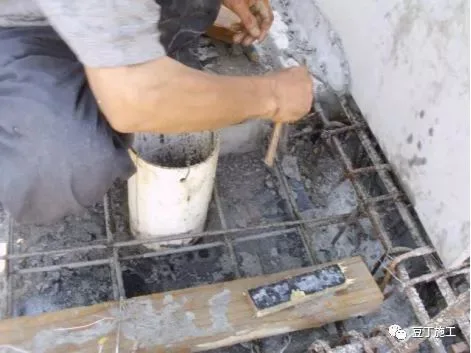
6. Grouting ports are often not compacted properly. Prevention includes using a 1:3 dry hard cement mortar mixed with micro-expansion agent to fill tightly, followed by inspection with a small hammer after drying.
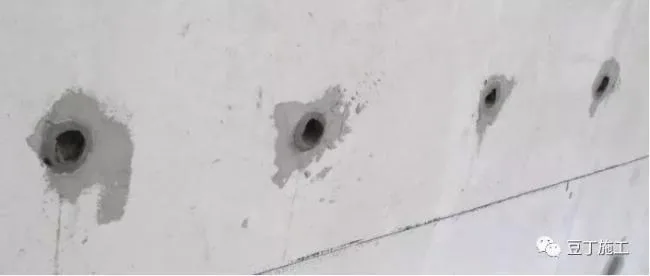
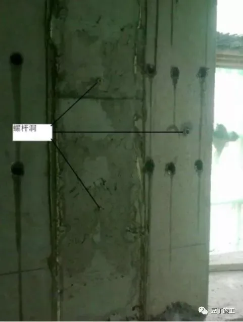
7. Poor design of embedded bolts, on-site omissions, and extensive substitution with expansion bolts have blocked electrical conduits and increased costs.

Prevention measures:
- The design department provides embedded bolt positioning diagrams based on the 3D model, considering diagonal support lengths and angles. They must check for conflicts with conduits or wire boxes during construction and supply updated drawings promptly.
- On-site quality inspectors verify embedded bolt positions, fixation, completeness, exposed thread length, and protection. Any collisions with conduits or wire boxes should be reported to project technical leaders or the design department for modification suggestions.
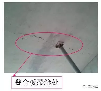
8. Analysis of cracks in composite panels:
- Design issues include unreasonable local segmentation and oversized components with only 50mm thickness.
- Processing plant issues: Components poured before March experienced premature formwork removal, disturbing internal steel bars. Strength tests showed low concrete strength (10-13MPa), leading to micro-cracks.
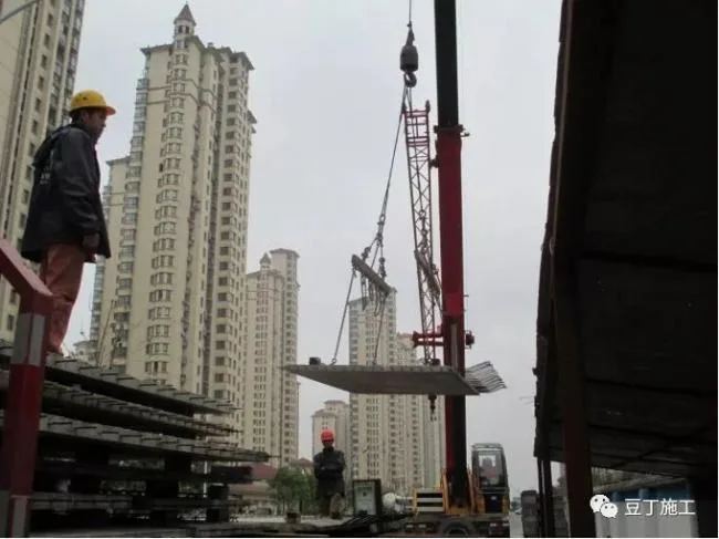
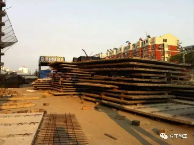
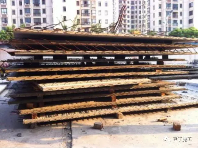
- Site issues: Improper unloading, stacking, and hoisting with insufficient lifting points, excessive stacking height (11-13 layers), mixed components, asymmetrical cushion blocks, and bending or deformation.
- Incorrect support positioning and orientation (should be perpendicular to steel trusses).
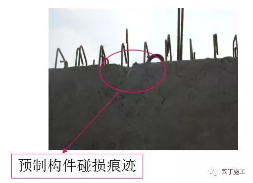
8.1 Only four lifting points were used when unloading laminated panels, causing damage.
8.2 Improper stacking of laminated boards without following specifications led to disturbance and splitting.
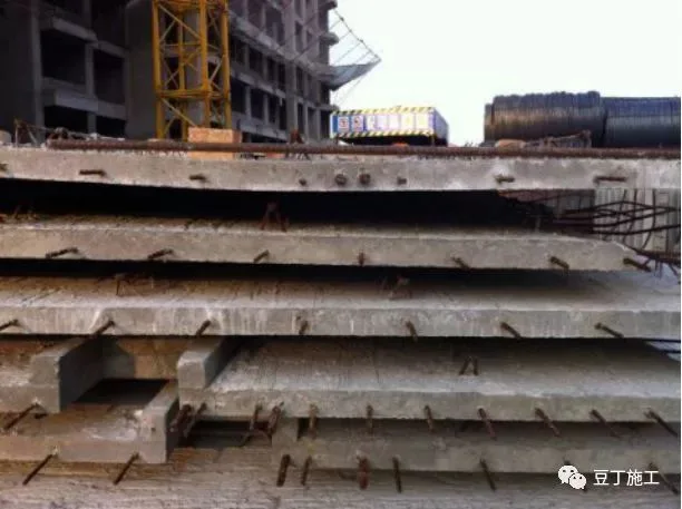
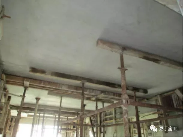
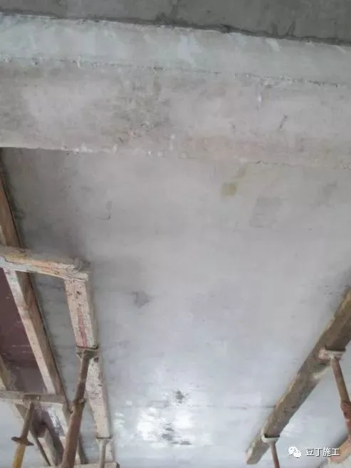
8.3 After installation, composite panels were not supported according to regulations, resulting in cracking. On-site crack repair involves epoxy resin pressure grouting.
Prevention measures:
- The design department marks the center of gravity, suspension point positions, and compass directions on component design and processing drawings.
- The processing plant marks lifting point positions and quantities clearly on component drawings and composite panels.
- Ensure molding strength meets design requirements and strengthen curing.
- Technicians conduct technical briefings before molding, transport, stacking, and lifting. Lifting points and slings must match design, and each sling must be tested for load.
- Stacking sites must be flat, components stacked per specifications with aligned blocks, and stacking height limited to six layers.
- Horizontal components should be lifted slowly, placed quickly, then lowered slowly.
- Temporary supports for horizontal components must be spaced no more than 0.5m apart and along the length no more than 2m apart. For spans over 4m, add mid-span supports with arching height not exceeding 3‰ of the span.
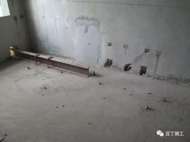
9. Delay in installing stair treads resulted in lack of protection awareness for finished products, posing safety hazards.
10. Incorrect platform elevation and insufficient inspection (evident from hole openings) pose hoisting safety risks. Debris left uncleaned affects grouting quality.
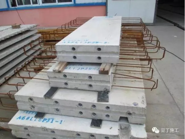
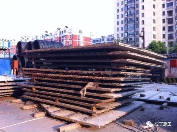
11. Issues with on-site acceptance and stacking of prefabricated components.
Problem description: Prefabricated components are stacked randomly, with wooden blocks in upper and lower rows misaligned, increasing the risk of cracks.
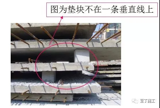
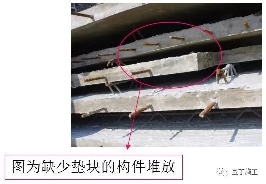
Handling measures:
- Ensure stacking sites are flat. If uneven, adjust cushion blocks so the bottom blocks are on the same plane.
- Place bottom prefabricated components flat and evenly stressed.
- Limit laminated board stacking to no more than 10 layers, preferably 6-7.
- Never omit cushion blocks between boards; vertical blocks must align in a straight line.
- All cushion blocks must comply with specification requirements.
12. Unreasonable suspension point design.
Problem description: Significant cracks and damage occurred during on-site lifting.
Root cause: The prefabricated components’ design was flawed, and suspension points were poorly located.
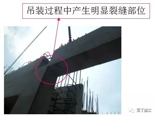
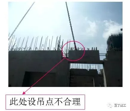
Handling measures:
- Remove components with poorly designed suspension points from the site.
- Request redesign of suspension point locations.
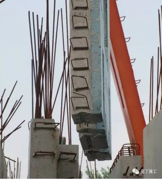
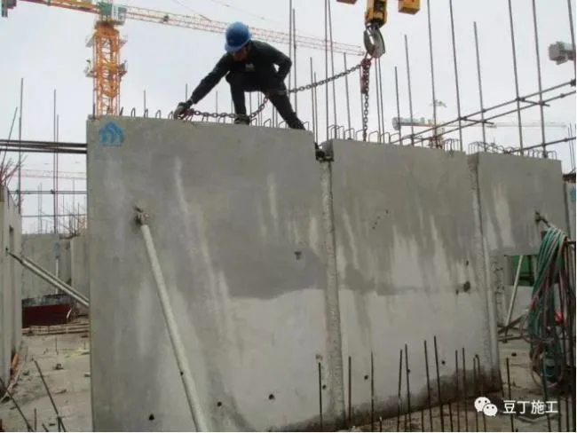
13. Prefabricated wall panel lifting deviation.
Problem description: Significant deviation of prefabricated walls severely affects project quality.
Root cause: Errors occurred during night-time wall calibration.
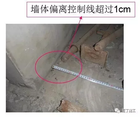
Handling measures:
- Correct the wall position.
- Construction units should strengthen on-site management to prevent recurrence.
- Supervisory units must enhance inspection and supervision.
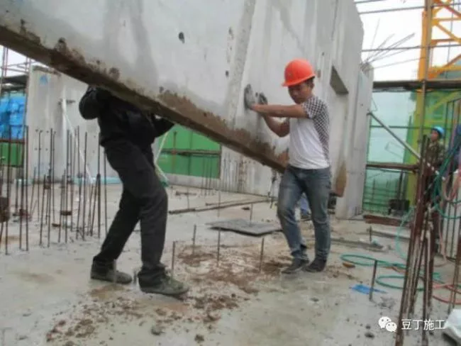
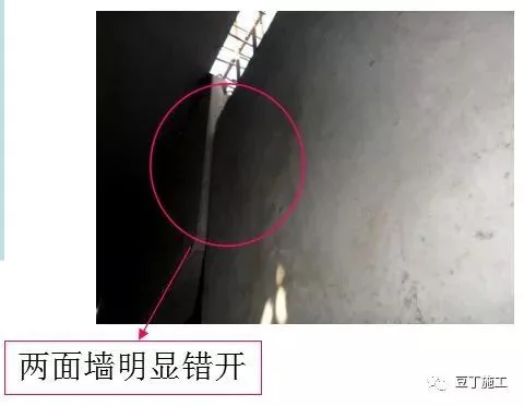
14. Lifting collision damage.
Problem description: Visible cracks appeared in the mortar joints of tight wall connections.
Root cause: During lifting, the on-site supervisor collided with a fixed prefabricated wall, causing loosening.
Handling measures:
- Recheck wall verticality, adjust fixing bolts, and ensure stability.
- Reconstruct dense mortar joints to ensure compactness.
- Strengthen lifting management, standardize procedures, and avoid rough handling.
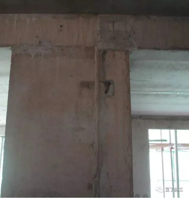
15. Missing fixing points for embedded bolts in prefabricated component slant supports.
Problem description: Missing or offset embedded bolt fixing points may cause hidden dangers, such as damage to embedded conduits from later floor slab drilling and reinforcement planting.
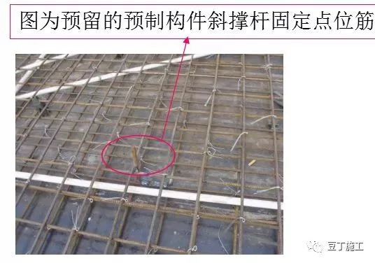
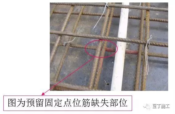
Handling measures:
- Require construction units to determine and mark all fixing point positions based on drawings. Before concrete pouring, carefully inspect quantity and quality of reserved fixed point reinforcements to ensure no omissions or deviations beyond standards.
- Supervision and engineering departments should strengthen acceptance work for these areas.
16. Leakage and grooving of prefabricated component pipelines.
Problem description: Some prefabricated components had missing or misaligned embedded pipes, leading to chiseling grooves and potential component damage during installation.
Root cause: Omissions of pre-embedded pipe fittings during processing and failure to install pipelines according to drawings.
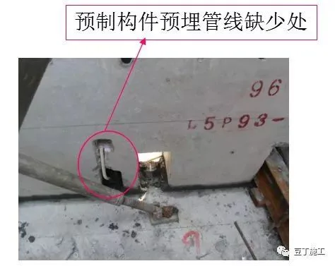
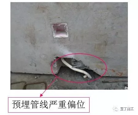
Handling measures:
Strengthen management to ensure pre-embedded pipelines are constructed strictly according to drawings, with thorough inspections before concrete pouring.
17. Insufficient grouting of prefabricated components.
Root causes:
- Incorrect grouting material mix.
- Drying of bellows.
- Blocked or loosely sealed grouting pipelines and joints, causing leakage.
- Operator negligence.
Prevention measures:
- Strictly follow preparation instructions for ratios, feeding sequence, mixing method, and timing.
- Check grouting pipes and joints for unobstructed flow before hoisting. Moisten pipes half an hour prior with minimal water to avoid accumulation.
- Use pressure grouting machines to fill holes continuously in one go; compact and smooth surfaces before final setting.
- Use grouting material within 40 minutes of mixing.
- Train and manage operators to raise quality awareness.
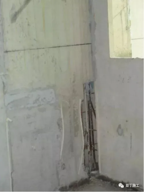
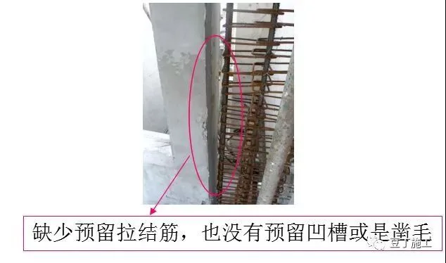
18. Lack of reserved tension bars in prefabricated components.
Root cause: Design flaws with insufficient attention to critical nodes.
Handling measures:
- Construction unit should strengthen inspection of cast-in-place nodes; supervision and owner’s engineering departments must conduct re-inspections.
- Request design revisions to add tension bars where missing and carefully review designs for omissions.
- For produced but uninstalled components, add wall reinforcement on-site; for installed ones, reinforce joints later.
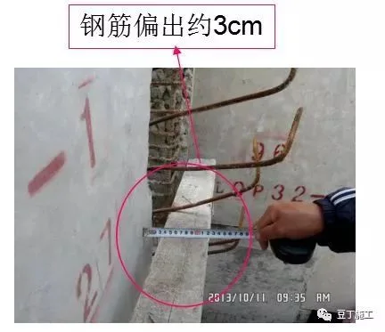
19. Steel bar deviation in prefabricated components.
Root cause: Vertical steel bars were not properly secured before floor concrete pouring, and concrete pouring and vibration caused bars to shift.
Prevention measures:
- Use steel reinforcement positioning frames and supporting bars to ensure accurate rebar placement before concrete pouring.
- After pouring, recheck reserved reinforcing bars’ center positions against layout plans and boundaries. Correct deviations over 10mm as per drawings.
20. Reinforcement connection issues.
Problem description: Loose sleeve joints, overlapping overlaps, and severe bending of steel bars at cast-in-place nodes pose structural safety risks.
Root cause: Improper worker operation and insufficient on-site supervision.
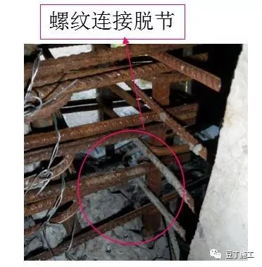
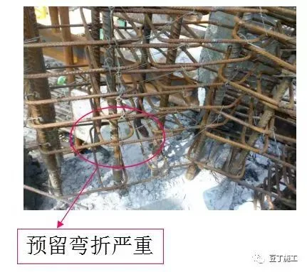
Handling measures:
- Protect steel sleeve joints during platform concrete pouring to prevent debris contamination.
- Workers must clean and oil steel bars before connecting to meet quality standards.
- Management should strengthen on-site supervision, inspect all sleeve joints, and conduct re-inspections to promptly address issues.
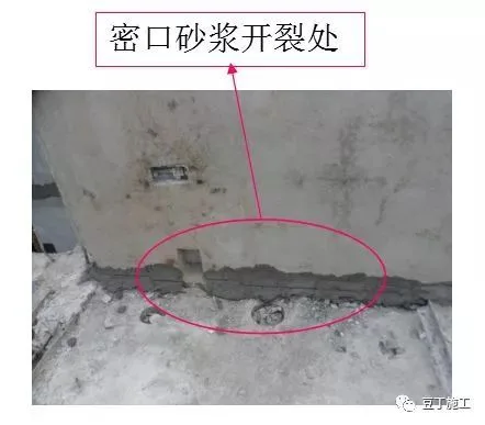
21. Excessive sealing mortar at stairwell exterior wall horizontal joints seriously affects grouting quality.
Root cause:
- The lower prefabricated components lacked tongue retention, creating excessive horizontal gaps.
- Construction units neglected management responsibilities.
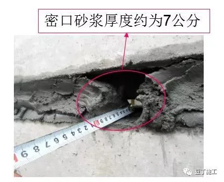
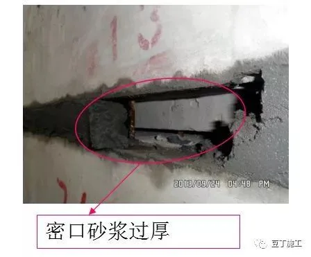
Handling measures:
- Re-implement blocking measures and submit plans for approval before execution.
- Require stronger on-site management to prevent excessive mortar use compromising grouting quality.
- Improve NPC technical specifications with clear guidelines on sealing mortar thickness and volume ratios to support inspection and acceptance standards.
22. Cleaning issues before concrete pouring.
Problem description: Inspection revealed concrete fragments and debris remaining in node areas.
Solution: Construction units must enhance management, ensure process continuity, and verify all preparations before proceeding to subsequent steps.
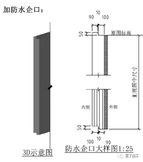
23. Missing structural key grooves.
Root cause:
- Enterprise practices not meeting requirements.
- Incorrect groove placement.
- Template deformation.
Preventive measures:
- Create tongue and groove molds according to design drawings, with trapezoidal grooves: top width 90mm, bottom width 100mm, height 50mm, and a 10mm slope for easy demolding.
- Snap template lines accurately on platforms and install templates accordingly.
- Ensure no deformation occurs during subsequent construction after template installation.
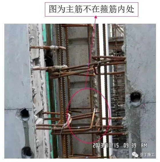
24. Main reinforcement located outside the hoop reinforcement.
Problem description: Main reinforcement at wall nodes not enclosed by hoop reinforcement poses structural safety risks.
Root cause: Deviation of main reinforcement and insufficient hoop reinforcement length reserved at the prefabrication factory.
Handling measures:
- Implement remedial strengthening measures.
- Enhance on-site construction management to prevent steel bar deviation.
- Provide timely feedback to the processing plant and redesign hoop reinforcement length to avoid recurrence.
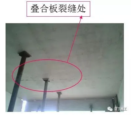
25. Cracking in laminated panels.
Root cause: Insufficient curing time; laminated panels had not reached specified strength.
Handling measures:
- Require construction units to replace affected composite panels with qualified new ones. Considering project progress, submit special repair plans for approval before execution.
- Strengthen on-site management to ensure composite panels reach 100% strength before dismantling and hoisting.
- Supervisory units must reinforce inspection and supervision efforts.


Must log in before commenting!
Sign Up