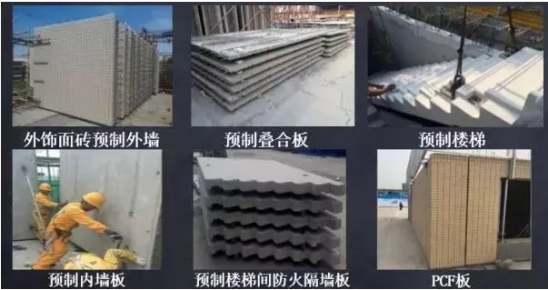
The assembled integral reinforced concrete shear wall structure primarily consists of prefabricated shear walls, composite beams, and composite panels designed for prefabricated housing. These components are connected using effective cast-in-place methods to form a complete reinforced concrete shear wall system.
Project Overview
Ground floor area: 100,000 square meters
Building height: 60 meters / 32 meters
Number of floors: 21 / 11 / 10 / -1 / -2 / -3
Component types: Eight categories, including prefabricated exterior wall panels, prefabricated interior wall panels, prefabricated composite panels, and more.
Detailed Design Development
Using actual office building project samples, building and decoration models are created, including backfill soil, ground layers, walls, roof decoration layers, staircase decoration layers, doors and windows, floor-to-ceiling curtain wall windows, railings, step water drainage, steel canopies, ceilings, and other component families. Parameter settings are applied to these models, which are developed in stages to provide detailed statistics. This process ensures proficiency in architectural and decoration modeling and enables efficient creation of project-specific models.

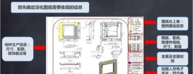
Preparation of Prefabricated Assembly Drawings – Information Collection
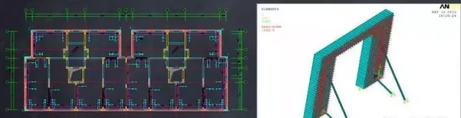
Preparation of Assembly Drawings
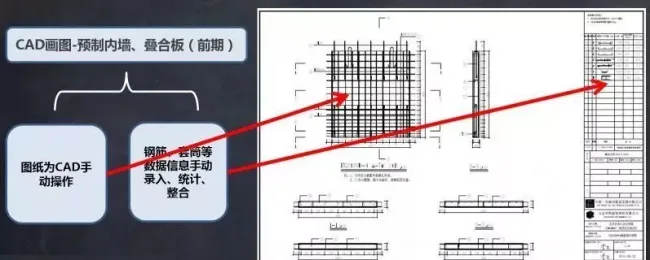
CAD Drawings
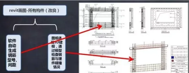
Revit Drawings
Prefabricated Component Processing Deployment
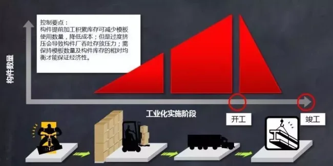
Key Control Points
Pre-processing components and maintaining inventory can reduce the number of templates required and lower costs. However, excessive stockpiling may cause storage pressure in the component factory. It is important to balance the number of templates and component inventory to optimize economic efficiency.
Common Issues During Component Processing and Storage
1. Identification of components produced earlier becomes unclear due to extended storage time.
2. Transportation of components is restricted to specific times due to traffic regulations.
3. Repairing damaged prefabricated components, especially the concrete at external corners, is challenging and may cause further damage.
Corresponding Measures
1. Plan transportation routes carefully and coordinate the delivery and unloading of components at the construction site efficiently.
2. Implement protective measures for finished products during transportation and storage.
On-site Construction Deployment of Components
Detailed design of components includes preparing plans for inclined supports for wall panels and independent supports for composite panels. The pre-embedded positions for temporary fixed diagonal supports in prefabricated wall panels and composite panel connectors are determined through calculation. Independent support force models are calculated, and structural performance tests are conducted to ensure safe and reliable on-site component installation.
Precautions for Road Transportation
1. The on-site road is long and U-turns are strictly prohibited.
2. The minimum turning radius must allow a 16-meter trailer to make a 90-degree turn.
3. To accommodate simultaneous construction activities, transportation should be staggered to avoid concurrent unloading of trucks and concrete mixers.
Precautions for Component Storage
1. The unloading area must consider the lifting capacity and operational efficiency of the tower crane.
2. Plan the number of templates stored on-site in advance, and require the component factory to submit a component allocation plan.
3. Ensure construction efficiency is not compromised on-site, and the factory should transport components at full capacity whenever possible.
Component Installation Organization – Workflow Division and Scheduling

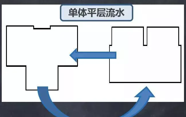
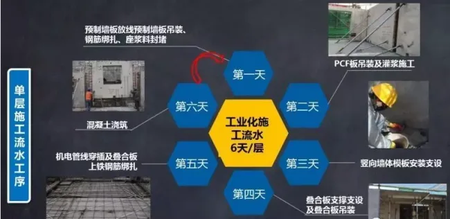
Single-layer Construction Workflow
Article source: National Standard Platform


Must log in before commenting!
Sign Up