Case 1: This hydropower project primarily focuses on power generation, while also considering additional benefits such as tourism and ecological compensation. It features an installed capacity of 113 MW, with a storage capacity of 1.35 × 10⁸ m³ at the normal water level, 2.054 × 10⁸ m³ at the flood control level, and a regulating storage capacity of 0.176 × 10⁸ m³. Classified as a second-class large (2) type project, it utilizes BIM software technology during the construction drawing design phase to significantly reduce defects, errors, clashes, and omissions, thereby greatly improving design efficiency.
The 3D structural layout diagram of the flood discharge and sand flushing gate shown in Figure 1 is a planar section directly extracted from the 3D model on the Inventor 3D modeling platform. This method allows for convenient and rapid generation of accurate construction drawings. Figure 2 presents the 3D model of the upper structure of the flood discharge and sand flushing gate, also created on the Inventor platform. This model can be exported in *.sat format and imported into analysis programs such as ANSYS or PKPM for stress and strain evaluation.
Figure 3 displays a 3D model of the power plant building created on the Revit modeling platform. The model can be exported in *.sat format and imported into Navisworks software for collision detection. The software produces a detection report that guides optimization in the design process.
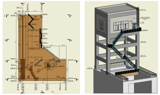
Figure 1: 3D structural layout of flood discharge and sand flushing gate Figure 2: 3D model of upper structure of flood discharge and sand flushing gate
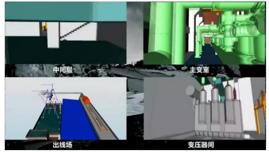
Figure 3: 3D model of the power plant building
Case 2: The second phase of a 35kV substation project covers an area of 3,004.2 m², with a total construction area of 168.8 m² and a road area of 440 m². The main roads are both 4 meters wide. The 35kV and 10kV components are arranged in a conventional outdoor layout. The main control building is a single-story structure housing a control room, duty room, communication room, and living and production auxiliary room. Additionally, there is one reserved expansion site in the main transformer area and two construction sites in the capacitor area.
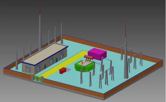
Figure 4: Overall layout model of the second phase of the substation project
The overall layout model shown in Figure 4 was developed on the Inventor 3D modeling platform. It includes detailed building models (such as the duty room, apron, on-site roads, and fire fighting rooms) as well as electrical equipment models (outgoing line racks, lightning rod towers, transformers, and capacitors). This comprehensive model can be imported into Navisworks software via interface integration. Surface parameters can be modified within relevant modules and then transferred to Infraworks for large-scale scene construction.
The model also supports direct collision detection within Navisworks, producing error evaluation reports that facilitate efficient corrections. Furthermore, the upper structure model of the duty room can be exported and imported into structural software like PKPM for stress and strain analysis.


Must log in before commenting!
Sign Up