BIM models can be utilized throughout the entire lifecycle of deep excavation projects. They encompass information applicable to various stages, including design, construction, and monitoring of deep excavations. Before constructing deep foundation pit support structures, it is essential to develop a visual 3D solid model that adheres to the Industry Foundation Classes (IFC) standard. This model should include detailed physical characteristics such as geological data, engineering hydrogeological information, support structures, and the surrounding environment.
Besides representing the 3D geometric information and topological relationships of components involved in deep foundation pit engineering, the model must also incorporate additional relevant data. This includes component names within the support system, types of support systems, materials used, and the physical and mechanical properties associated with the engineering project.
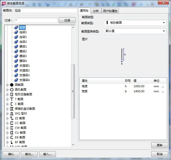
Figure 1: Sectional storage of retaining beams in deep foundation pit engineering
To support multi-condition analysis and comparative assessments of technological and economic factors during construction, the BIM model should also integrate construction-related information. This includes construction procedures, schedules, cost budgets, quality monitoring, and resource allocation (personnel, materials, and machinery). Furthermore, maintenance data such as safety performance, material durability, and logical relationships between various components should be incorporated.
Ensuring the completeness and accuracy of this integrated data within the BIM model lays a solid foundation for the seamless execution of subsequent stages in deep foundation pit engineering.
Currently, while BIM software systems for construction engineering are well-developed, specialized BIM modeling systems tailored for deep foundation pit engineering are not yet widespread in the market. This gap presents significant opportunities for developing object-oriented BIM modeling systems specifically designed for deep excavation projects.
Object orientation involves identifying common components or structural parts within deep excavation engineering and creating standardized, specialized component objects. In Tekla software, for example, this concept is implemented through components.
Based on the principle of component creation, we will demonstrate the application of parametric design during the design phase of deep foundation pit engineering. Since Tekla software primarily focuses on industrial and civil building modeling, its default section libraries mainly contain standard building component sections. However, custom cross-sections can be created as needed. For instance, Figure 1 shows the cross-section library for deep foundation pit engineering purlins.
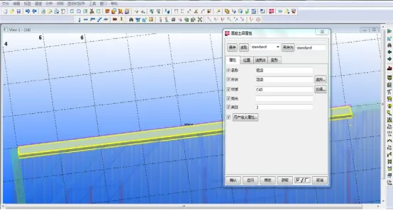
Figure 2: Parameterized Components
When using BIM software for modeling deep foundation pit projects, parametric design enables dynamic creation and modification of component models. This approach greatly simplifies later revisions of construction drawings and scheme adjustments. Parametric modeling is widely applied in industries such as mechanical engineering with software like SolidWorks and Pro/Engineer.
Taking the crown beam as an example in deep foundation pit engineering, Figure 2 illustrates the parametric design of crown beams using Tekla software. All parameters of the crown beam can be freely adjusted, with changes instantly reflected in the 3D model of the component.
Each component possesses a unique data information model. By modifying different parameters within these models, 3D component models can be rapidly generated and integrated into deep foundation pit projects. However, due to the complexity of these components, limited standardization, and poor universality, parametric modeling requires creating project-specific component types.
This challenge contributes to the current difficulties in applying BIM technology broadly to deep excavation engineering modeling.


Must log in before commenting!
Sign Up