Abstract: Roof engineering involves complex shapes and diverse functions, playing a crucial role in the overall construction process. The quality of roof engineering significantly impacts the later stages of building use. Consequently, roof engineering has always been a key focus during inspections. In high-quality projects, there are elevated demands for roof construction quality and pipeline layout, making traditional two-dimensional construction techniques insufficient. The Giant Stone Technology Center project applies BIM technology to the detailed design of roofs. This application not only enhances the roof’s overall aesthetics but also facilitates precise management of roof construction, material savings, and guides the achievement of excellence.
Keywords: BIM technology, roof detailing, optimization management, equipment foundation, integrated pipeline
Project Overview
The project concerns the Jushi Technology Center, serving as the headquarters office building for Jushi Group. It is situated at the intersection of Fengqiao Road and Fenghuanghu Avenue on the northern bank of Fenghuanghu in Tongxiang City. The site covers 23,292.5 square meters, with a total construction area of 61,617.27 square meters. The complex comprises the East and West Towers, podiums A and B, and an underground garage, with a building height reaching 119.9 meters.
The towers utilize a steel frame and core tube structure, while the remaining buildings employ a frame structure. The East and West Towers feature elevated corridors spanning approximately 20 meters, located between 47.3 meters and 62.6 meters in height, constructed with steel structures and truss floor support plates. The project includes a pedestrian roof area of roughly 3,121 square meters.
Technical Challenges in Roof Construction
The roof construction at Jushi Technology Center involves a large volume of work, a tight schedule, and high complexity. It incorporates multiple disciplines including civil engineering, curtain walls, water supply and drainage, fire protection, HVAC, and electrical systems, all working simultaneously in a constrained space, which complicates coordinated construction.
Furthermore, the roof space is limited and contains numerous specialized equipment. Equipment positions and auxiliary electrical boxes are dispersed across design drawings, complicating unified management during later stages. The project aims for the prestigious “Luban Award,” which demands a well-organized roof layout featuring flat, neatly arranged tiles, uniform brick joints, straight lines, clear drainage slopes, and overall harmony. Exhaust holes, drainage outlets, exhaust pipes, and equipment foundations must be aligned and centralized.
Deepening the Application of BIM
3.1 Roof Analysis
A comprehensive review was conducted, compiling building structures, equipment, curtain walls, and design change documents related to the roof. Any ambiguous information was flagged, and all relevant data for modeling was organized into tables (see Figure 1). For instance, actual equipment specifications and minimum size requirements for equipment foundations were confirmed with manufacturers, who provided detailed parameter specification tables. Additionally, pipeline types, sizes, materials, and connection methods were cataloged to facilitate modeling.
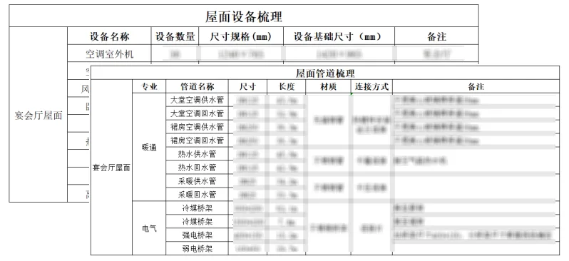
Figure 1: Information Sorting for Roof
3.2 Model Establishment
Using construction drawings, design change orders, and organized data tables, three-dimensional models of roof air ducts, fresh air conditioning rooms, water pipes, cable trays, curtain walls, and skylight courtyards were created in software (see Figure 2). During modeling, drawing issues were further identified (see Figure 3) and resolved through communication with design teams. Unlike traditional CAD flat drawing reviews, 3D modeling intuitively reveals design inconsistencies, enabling development of implementation standards tailored to project specifics, thereby improving model accuracy and quality.
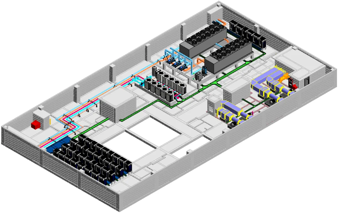
Figure 2: 3D Model of Roof Engineering
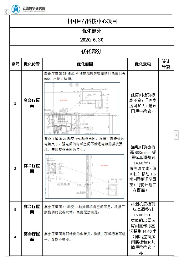
Figure 3: Identified Drawing Issue
3.3 Roof Layout
Based on completed models across disciplines, the equipment foundation locations, grid joints, and gutter layouts were preliminarily positioned to ensure uniform and logical roof partitioning, accurate slopes, efficient drainage, overall coordination, and visual appeal.
The grid joints on the floor slab were detailed in CAD drawings and preliminarily positioned. Dividing joints were placed on the roof leveling layer, evenly spaced and symmetrical, complying with partition specifications, with a width of 10mm. Gutters were arranged perpendicular to drainage slopes along the inner side of parapet walls, with widths adjusted based on the square brick layout (see Figure 4).
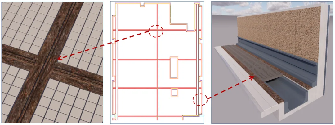
Figure 4: Roof Grid Joints and Gutters
3.4 Roof Tile Layout
The banquet hall roof covers a large area with numerous roof-mounted equipment. To control construction quality and minimize material loss, a combination of CAD 2D brick layout and BIM 3D brick layout was employed. Based on the preliminarily determined grid joints, bricks were arranged according to specifications including joint width and layout. Multiple starting points were optimized, and the final layout was modeled in BIM software to guide construction (see Figure 5).
The square tiles used are 100x100mm beige bricks with 10mm joint widths. Roof tile flatness, slope, and exhaust holes meet requirements, with straight and uniform longitudinal and transverse joints, all free from impurities.
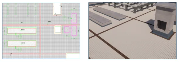
Figure 5: Roof Square Brick Layout Model
3.5 Equipment Foundation Optimization
Following preliminary equipment foundation placement, adjustments were made considering roof drainage direction and the square brick layout. For instance, the air-cooled heat pump unit on the banquet hall roof originally had a floor-standing strip foundation as per manufacturer data. However, constructing as designed would place the foundation too close to the curtain wall and electrical room walls, hindering maintenance. Thus, the equipment position was optimized.
Initially, a rotation from horizontal to vertical placement was considered, but vertical alignment was perpendicular to roof drainage and resulted in a nearly 13-meter-long foundation obstructing drainage. Hence, the equipment orientation remained unchanged, and foundation form was modified by replacing the strip foundation with an overhead column-beam foundation (see Figure 6).
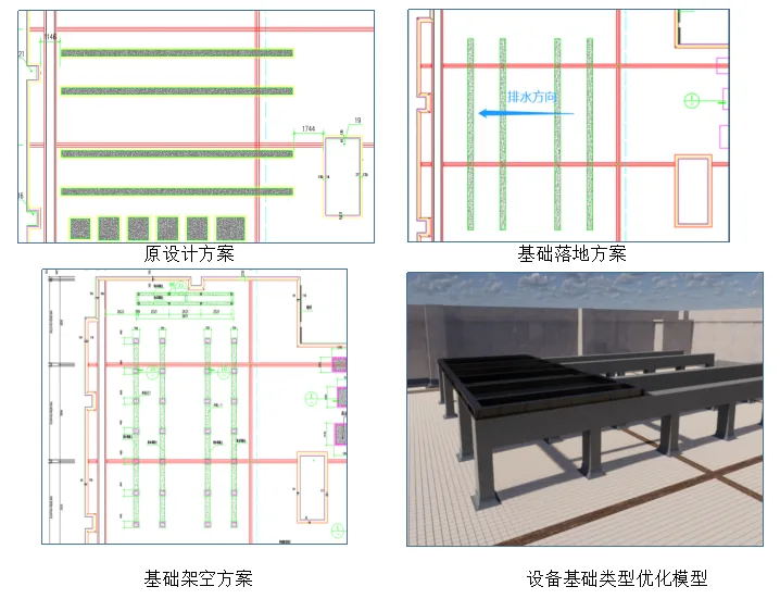
Figure 6: Equipment Foundation Optimization Process
3.6 Pipeline Optimization
Equipment models provided by manufacturers were integrated into the base layout. Pipeline branches were optimized based on equipment interface positions, taking into account pipeline shafts, air shafts, lighting shafts, high-voltage rooms, and roof machine rooms. Routing was refined to logically space pipelines, align same-discipline pipes in rows, minimize crossings and bends, and ensure functional connections. Maintenance channels were also planned to facilitate future installation and upkeep.
3.7 Support Positioning
Roof pipeline supports were arranged according to pipeline routes, utilizing comprehensive supports for grouped pipelines. Support lengths were adjusted based on pipeline quantity and diameter, with spacing aligned to specifications and square brick layout. Concrete supports were pre-cast at support landing points to ease later installation (see Figure 7).
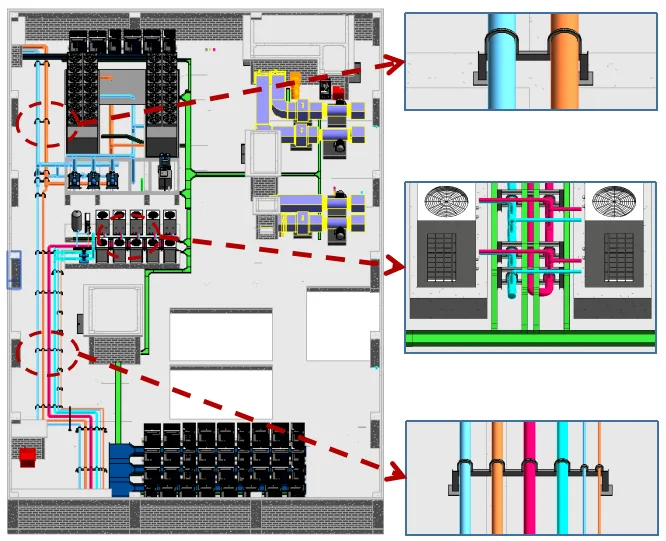
Figure 7: Comprehensive Pipeline and Support Layout Model on Roof
3.8 Scheme Presentation
After completing the detailed design, a roof walkthrough model was exported and combined with the model to present to the construction unit, general contractor, and subcontractors. This significantly improved clarity and accuracy of the presentation, enabling subcontractors to quickly grasp the construction plan. The model demonstrated detailed roof nodes and integrated optimization concepts, making the presentation more intuitive and enhancing understanding of construction techniques at critical locations.
3.9 Scheme Drawings
From the finalized model, 2D CAD plan drawings were exported for different construction stages. Basic plans guided foundation positioning, while pipeline layout drawings supported pipeline installation and support placement. Detailed roof construction plans were provided to better direct on-site work in conjunction with 3D model drawings (see Figure 8).
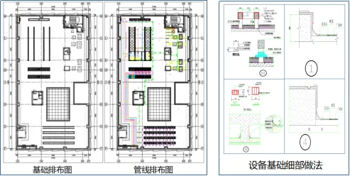
Figure 8: BIM Deepening Image
Four Key Highlights of BIM Deepening Application
4.1 Comprehensive Roof Equipment Layout Optimization
Before equipment placement, outdoor units were grouped centrally, with preliminary positioning based on actual manufacturer dimensions. It was discovered that some air conditioning units had restricted space when placed as originally designed, with locations near curtain walls impairing functionality. Also, the proximity to pipeline wells and the strong electrical room hindered installation and maintenance access.
After layout optimization, spacing between outdoor air conditioning units and foundations was increased based on actual dimensions. A roof lighting well was canceled to provide additional equipment space after consultations with construction and design teams. The east-west air-cooled heat pump units were repositioned north-south to avoid conflicts with electrical rooms. Equipment initially densely packed was shifted to more accessible positions, facilitating pipeline installation and rendering the roof layout more rational (see Figure 9).
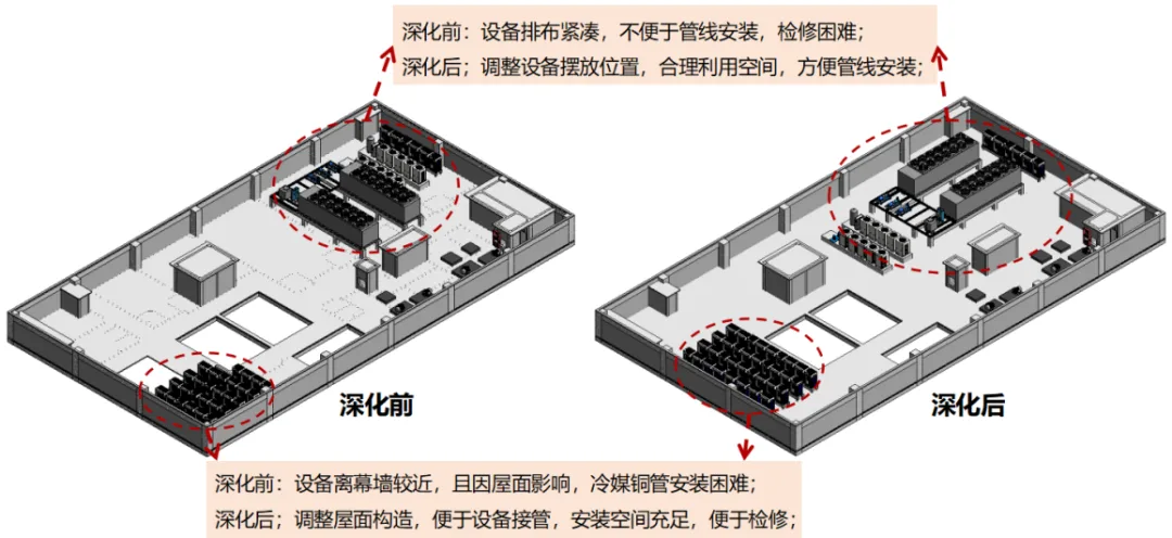
Figure 9: Roof Equipment Comparison Before and After Deepening
4.2 Optimization of Roof Maintenance Access
Roof detailing accounted for reasonable access routes and maintenance space. Steel ladders were installed in areas difficult to access. Pipeline routing was optimized to facilitate usage and upkeep. Post-optimization, the number of steel ladder installations decreased from five to three, enhancing overall accessibility (see Figure 10).
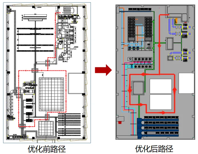
Figure 10: Roof Channel Layout Comparison Before and After Deepening
Five Benefits Analysis
5.1 Reduced Construction Duration
Prior to roof construction, BIM specialists developed a detailed roof layout plan. After review and approval by various parties, the general contractor created a construction schedule based on this plan, coordinating processes to avoid conflicts from simultaneous work by multiple units. Thanks to BIM-delivered construction drawings, no rework was necessary, allowing each unit to complete tasks ahead of schedule despite tight deadlines.
5.2 Material Savings
Roof detailing focused on tile arrangement to minimize cutting and material waste. After selecting the optimal layout, material quantities were calculated via the model to support procurement planning (see Figure 11), enabling refined material management and pre-planning. Post-completion, material loss rates were analyzed for audit and closed-loop management.
The project’s square brick consumption coefficient is 758.3 ㎡ / 990 ㎡ = 0.7659, significantly lower than Zhejiang Province’s benchmark of 0.8745, generating nearly 10% cost savings for the project department.
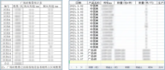
Figure 11: Project Material Statistics Table
Summary of Six Processes
To address limited roof space and multiple equipment challenges, BIM personnel collaborated with the project team to establish optimization principles. Equipment on the banquet hall roof was centrally placed, pipelines arranged in rows, and main roof access routes were kept clear. This resulted in a rational and aesthetically pleasing layout, supporting project optimization and improving management levels for roof construction, serving as a model for similar projects.
Upon completing the Giant Stone Technology Center project, BIM specialists developed a comprehensive BIM application workflow for roof detailing, standardizing and streamlining the process into a replicable and promotable method (see Figure 12).
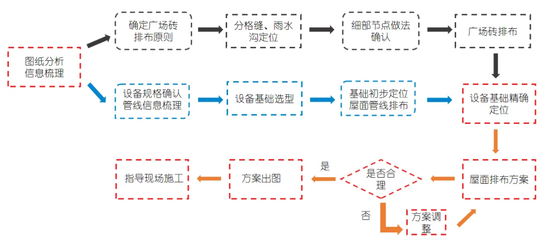
Figure 12: Roof Deepening Process Diagram
Seven Concluding Remarks
The advanced application of BIM technology in construction optimization effectively enhances inter-disciplinary construction efficiency, strengthens coordination of detailed designs across disciplines, and improves construction quality through quality control and optimized construction planning during execution.
This project leveraged BIM technology for robust theoretical guidance in project optimization management. Beyond roof detailing, the BIM team contributed practical results in site layout planning, main construction plan optimization, comprehensive underground pipelines, outdoor pipeline networks, and other early-stage applications, significantly elevating the project’s scientific and refined management standards.
This article systematically summarizes BIM technology’s application in roof optimization management, offering valuable reference and inspiration for similar enterprise projects.
References
Kong Xiangli, Li Chuan, Li Xiaolei, et al. The Application of BIM Technology in Roof Construction. China Real Estate Industry, 2017(20):1
Yang Chun, Long Hong, Wu Feng, et al. The Application of BIM Technology in the Deepening Design of Roofing Engineering. China Building Metal Structures, 2021(8):2
Wu Fengying, Cai Kaifa, Gu Jie. Application of BIM Technology in the Deepening Design of Roof Tile Arrangement – A Case Study of a Tertiary Comprehensive Hospital Roof. Fujian Architecture, 2021(2):4
Zhou Yong, Luo Fajiang, Li Peng, Wang Zhen, Ren Hongwei, Wu Hao. Application of BIM Technology in Roof Deepening Design. Construction Technology, 2016(S1):3
Copyright Notice
Graphics and Text by BIM Civil Engineering/Installation Application Department: Chen Bin, Shao Xianqing
Editor: Yunjiang Digital Research Institute – Dai Shuqin


Must log in before commenting!
Sign Up