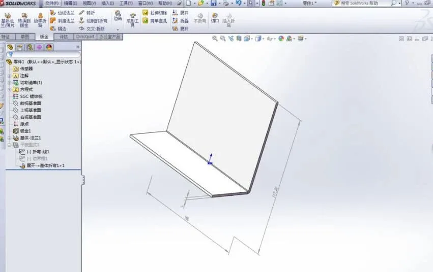
Start by drawing an open part diagram randomly within the sheet metal module.
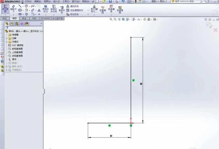
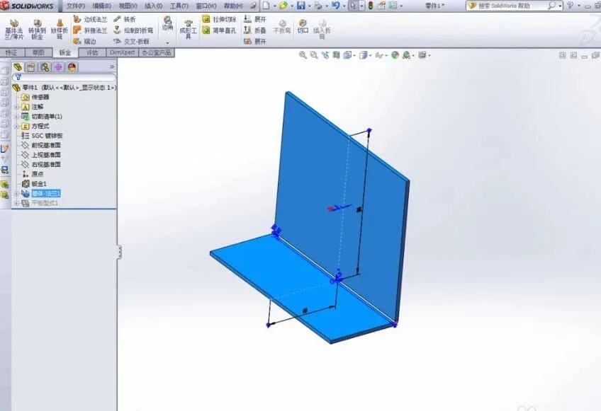
The created part appears as shown in the image. The next step is very important.
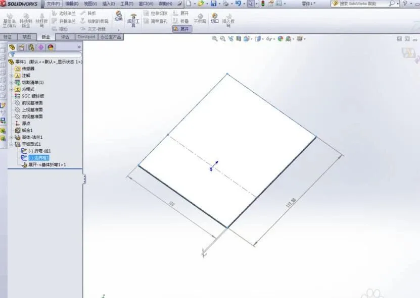
Unfold the sheet metal part and add dimensions while displaying the edge frame in the flat plate type from the design library. It is crucial to ensure that the dimension is marked as a Reference Dimension (this command is located on the left side of the image). Be sure to select it; otherwise, the unfolding dimensioning will not work correctly. The correct reference dimension will appear in gray, while incorrect ones will be shown in pink and cannot be exported.
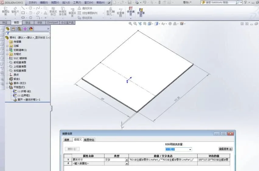
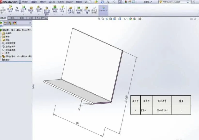
Next, customize the file properties of the subcomponent as shown below. The unfolding dimensions are linked: simply click on the previously marked dimensions and separate them using an asterisk “*”. The expanded size formula should be: length * width * plate thickness.
After completing these steps, make sure to fold the sheet metal parts back. Failing to do so may cause assembly relationships to become disorganized. If you find the gray dimensioning distracting in the viewport, you can hide it by clicking View > All Annotations.
Finally, during assembly, use the material list to review your parts and dimensions.


Must log in before commenting!
Sign Up