Originally designed for mechanical manufacturing, CATIA software features a user interface and human-computer interaction methods that differ significantly from other mainstream engineering drawing tools. Basic operations such as zooming and panning are handled differently in CATIA. Compared to other BIM modeling software, CATIA is also known to have a steeper learning curve. However, a notable feature of the CATIA interface is the operation process tree located on the left side, as shown in the image below. This tree records every step the user takes during the drawing process, providing clear visibility into the workflow.
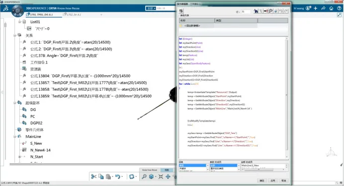
The process tree enhances the clarity of CATIA’s modeling workflow, making modifications and optimizations more convenient and efficient. In CATIA, every model entity begins with a planar sketch, from which the 3D entities are generated. The coordinate system of the sketch plane, the dimensions of the shapes within the sketch, and their positional relationships must all be defined parametrically. This structured approach makes the modeling process more complex and often requires extensive parameter input.
Nevertheless, this complexity allows CATIA to offer powerful parametric design capabilities, including variable-driven and post-parametric adjustments, which facilitate flexible modeling. Unlike many BIM drawing programs, whose main functions focus on drafting and rendering, CATIA is an integrated platform combining drawing, analysis, and simulation tools.
However, CATIA’s core strengths lie in mechanical engineering applications. Its development for the civil engineering sector is still emerging, and many fundamental civil engineering drawing functions remain incomplete. For example, in the CATIA V6 version discussed here, creating a 3D axis for a route involves first extending the route’s normal plane line into a surface, then projecting the route’s vertical curve onto this surface to generate the axis.


Must log in before commenting!
Sign Up