1. Application
Autodesk Inventor Professional offers a seamless integration of various products, providing a risk-free transition from 2D to 3D design. This allows you to convert to 3D at your own pace, protecting your existing 2D graphics and knowledge investments. It also ensures that you are working on the most DWG-compatible platform available today.
Autodesk Inventor software is a comprehensive set of design tools used to create and validate complete digital prototypes. This helps manufacturers reduce the need for physical prototypes and accelerate the launch of innovative products.
The Inventor product line transforms the traditional CAD workflow by simplifying the creation of complex 3D models. Engineers can focus on functional design implementation while quickly generating digital prototypes to validate designs and detect errors before production. This approach speeds up the entire process from conceptual design to manufacturing, making Inventor a top-selling product in its category for seven consecutive years.
Ideal Tool for Design Processes
Autodesk Inventor Professional supports designers in reusing existing DWG files within a 3D design environment, enhancing efficiency through digital prototyping. Inventor reads and writes DWG files directly, eliminating the need for file conversion. This allows for an unprecedented experience when creating 3D parts using valuable DWG resources.
In addition to powerful 3D design tools, Inventor facilitates smooth data exchange with manufacturing software from other vendors, simplifying collaboration between customers and partners.
Specialized Tools to Meet Design Requirements
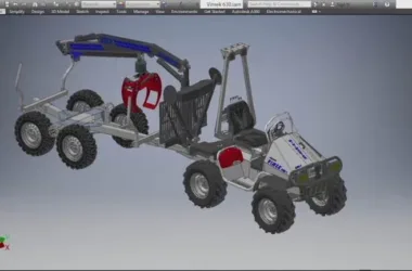
Inventor Professional offers a comprehensive, integrated design environment for creating and validating digital prototypes, covering appearance, structure, and functionality. The accurate 3D models support validation throughout the design process, reducing dependence on physical prototypes and minimizing costly design changes during manufacturing.
The software combines an intuitive 3D modeling environment with functional design tools. Users can create parts and assemblies, as well as intelligent components like steel structures, transmission mechanisms, pipelines, cables, and harnesses.
To verify designs before production—often a costly process—Inventor includes embedded motion simulation and stress analysis tools. Engineers can use these features to optimize and predict machine performance under real operating conditions using digital prototypes.
Generating manufacturing documentation from validated 3D prototypes helps reduce errors and Engineering Change Orders (ECOs). Inventor quickly produces accurate engineering drawings from 3D models and includes AutoCAD Mechanical, ideal for efficient 2D mechanical drafting.
Close integration with Autodesk data management software enables secure, efficient communication of design data. Design and manufacturing teams can collaborate early using the free Autodesk Design Review software to review, measure, mark up, and track design components. This improves reuse of critical design data, bill of materials (BOM) management, and team collaboration.
Autodesk offers various product configurations to meet specific functional needs. No other company matches Autodesk’s commitment to helping designers innovate and bring better products to market faster and more cost-effectively.
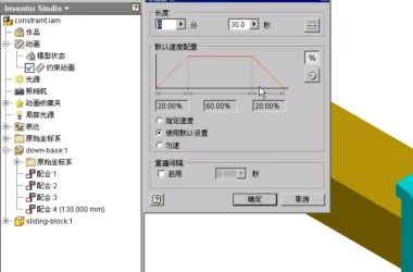
2. Motion Simulation
The motion simulation feature in Autodesk Inventor Professional helps users understand machine operation under real-world conditions, saving costs and time associated with building physical prototypes and consulting fees.
Users can apply loads, friction characteristics, and motion constraints based on actual operating conditions, then validate designs through simulation. Integrated with the stress analysis module, working conditions can be passed down to specific components for design optimization.
3. Enhanced Function Simulation
By simulating mechanical and electrical device operation, Inventor ensures design effectiveness while reducing prototype manufacturing costs. It calculates dynamic operating conditions throughout the entire cycle and allows precise adjustment of motor and transmission dimensions to withstand real workloads.
Analysis includes position, velocity, acceleration, and load on each component.
- Output to Stress Analysis: Motion simulation results can be imported into Autodesk Inventor Stress Analysis or ANSYS Workbench to predict stress and strain, enabling proper sizing of parts like pins and connectors.
- Constraint Conversion: Automatically analyzes assembly constraints, identifies rigid bodies, and converts them into accurate simulated motion connections. Users can select standard motion connections, add springs and dampers, define friction coefficients, and provide detailed descriptions.
- Load Definition: Apply various driving loads, torques, and time-based forces to study design performance under different conditions.
- Visualization: 3D animations demonstrate dynamic motion under load, fully reflecting design operation and performance.
- Point Trajectory: Track and display the movement of specific points on components during simulation, saving path sketches for future design reference.
- Grapher: Integrated graphical tools visualize motion characteristics over operating cycles, printing parameters like position, force, and acceleration for comparison.
- Microsoft Excel Output: Export XY plot data to Excel for detailed analysis and reporting.
Stress Analysis
The stress analysis feature in Autodesk Inventor Professional evaluates part strength and stiffness under load. Fully integrated with motion simulation, it uses accurate load data from simulations to perform precise stress assessments.
Easy-to-Use Embedded Analysis
Make informed design decisions based on analysis rather than intuition. Embedded stress analysis eliminates the need for CAD model conversions, making it more user-friendly than standalone tools. It allows you to evaluate deformation and stress extremes to improve part quality and ensure compliance with safety factors.
Integration with Motion Simulation
Analyze stress on moving parts at various points during the machine’s operational cycle by importing multiple time points from motion simulations to view detailed results.
Model Simplification
Finite Element Analysis (FEA) models can be simplified by suppressing features to improve analysis efficiency.
Thin-Walled Component Processing
Identify high-stress areas on thin metal parts, such as sheet metal, to ensure accurate analysis results.
Import Analysis Data into ANSYS
Advanced research can be conducted seamlessly by importing Inventor analysis data into ANSYS without costly data conversion.
Share Verification Results
Export analysis as AVI or graphic files to include in reports, providing intuitive and vivid demonstrations of assembly processes.
4. Pipe Laying Design
Autodesk Inventor Professional simplifies the creation of pipes, fittings, and hoses, saving users significant time.
Standardized piping tools ensure compliance with design rules such as minimum and maximum lengths, rounding increments, and bending radii.
Pipeline Design Dominated by Pipe Laying Function
Designing pipelines or ducts in complex assemblies and confined spaces is easier thanks to automatic pipe segment layout that adheres to preset styles. Users can choose pipe laying methods based on length standards and bending radius, or manually define pipelines through 3D sketches and editing tools. Automatic and user-defined pipe segments can be combined for maximum control.
Accessories Library
Improve quality and organization by selecting parts from a comprehensive library of industry-standard fittings, pipes, and hoses (ANSI, DIN, ISO, JIS). Users can add or modify properties like part numbers and control file names for easy referencing.
Hose
Use 3D digital prototypes to ensure hose and accessory designs are manufacturing-compatible. The system inserts suitable accessories and checks minimum bending radii, automatically updating hose lengths for manufacturing.
Hard Pipe Pipeline
Create rigid pipes with any number of bends, custom angles, and radii. Radius and rotation control points help shape the pipe precisely.
Pipe Fitting Style
Design pipelines that automatically adhere to existing standards, enhancing quality and manufacturability. Define fitting styles for threaded, welded, and flanged connections. Styles enforce design rules such as minimum pipe segment length, bend radius, and maximum joint spacing.
New Feature: Pipelines Meeting Hygiene Standards
For industries like pharmaceuticals, food processing, and personal care, pipelines must follow sterile and hygienic standards. For example, pipelines should have appropriate slopes to meet drainage requirements specified by the American Society of Mechanical Engineers for biological processing equipment.
Create a Pipeline
The fill pipeline tool automatically populates pipelines with real parts that meet manufacturing standards. It converts pipe, fitting, and flexible hose pipelines into solid models, placing fittings and segments as needed. Standard parts facilitate quality control and interference checks. Pipe joints are automatically added when pipes reach maximum lengths.
Layout Documentation
Link engineering drawing creation to design changes to minimize errors and costs. Drawings update automatically with 3D design modifications. ISOGEN PCF file output enables isometric pipeline diagrams in third-party software like Alias ISOGEN. ASCII pipe bending tables provide data for pipe bending machines.
5. Wiring Harness Design
Autodesk Inventor Professional supports cable and harness design using wire lists exported from circuit design software, including AutoCAD Electrical.
Integrating cables and wiring harnesses (including flexible ribbon cables) into digital prototypes enables accurate path length calculations, avoids tight bending radii, and ensures mechanical-electrical component compatibility—saving significant time and costs.
Wire Harness Design Guided by Wiring Function
Designing cables and harnesses in a 3D environment reduces manufacturing issues, facilitates drawing output, and avoids later engineering changes.
Conductor
Built-in electrical and mechanical data verification optimizes wire bundle designs. All wires and connectors in the wire table become part of the 3D cable model.
Wire Table Import
Maintain electrical design intent and minimize errors by quickly importing wire tables from AutoCAD Electrical or other software. Detect and correct missing connectors, pins, and wire definitions.
Wire Routing
Arrange thousands of wires efficiently while controlling their paths. Manual wiring requires selecting paths clearly; interactive routing selects start and end points for algorithmic shortest path calculation; automatic routing finds the shortest path among all options.
Define the Wiring Harness Path
Optimize assembly design to ensure adequate space and reduce manufacturing errors. Define 3D routing paths by selecting points, creating virtual pipe segments associated with the model. Add or move points to shape the harness accurately. The harness updates automatically with component design changes.
Ribbon Cable
Create ribbon cables integrated into 3D prototypes to minimize electronic design errors. Control twisting and folding positions between joints.
Joint Release
Create customized connector libraries to promote preferred connectors in electrical designs. Inventor includes a rich connector library for easy selection and placement. The Resource Center offers an editor for adding user-defined connectors and modifying properties like part numbers and file names.
Wire Harness Verification
Ensure cable quality and manufacturability by adhering to design standards. Inventor automatically calculates parameters such as harness diameter, bending radius, and wire length when wiring harnesses change, eliminating manual measurements and reducing errors.
Wiring Harness Documentation
Create manufacturing documents before production. Built-in cable and harness symbols allow detailed assembly documentation. Tools include:
- Automatic wiring diagrams for 3D documents of wiring harnesses, cables, and ribbon cables, updating automatically with design changes
- Generation of reports such as wire tables, terminal diagrams, and profile tables for design and manufacturing
- XML output files transmitting final wire connection information for schematic creation in AutoCAD Electrical or other software


Must log in before commenting!
Sign Up