On-Site Construction Layout
1. Requirements for On-Site Construction Layout
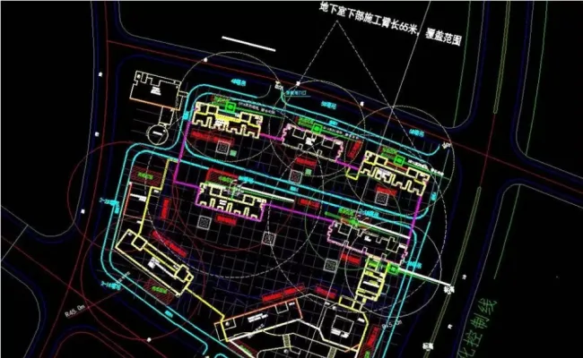
General Site Layout
Ensure smooth transportation of components through designated entrances, exits, and access routes.
The type and arrangement of lifting equipment must meet the requirements for component hoisting.
The yard layout should be standardized, logical, and efficient.
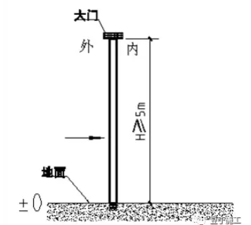
Component Vehicle Entry and Exit Specifications
If there is no ramp at the access entrance, the clear height (H) inside the construction access gate must be at least 5 meters.
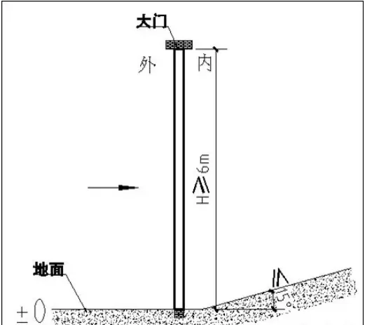
When a ramp is present at the entrance, the clear height (H) must be at least 6 meters, and the ramp slope should not exceed 15°.
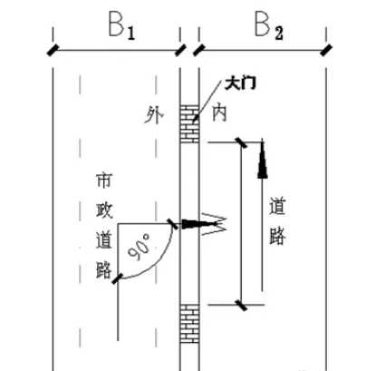
If the municipal road width is at least 8 meters (B1 ≥ 8m), the gate width must be no less than 12 meters (W ≥ 12m), and on-site road widths must be at least 8 meters (B2 ≥ 8m).
For municipal roads 10 meters or wider (B1 ≥ 10m), the gate width should be at least 9 meters (W ≥ 9m), and on-site roads must be at least 16 meters wide (B2 ≥ 16m).
Requirements for On-Site Road Layout
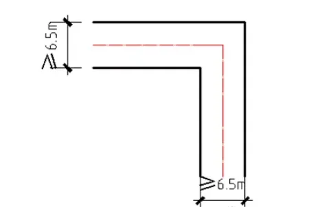
Right-angle turns require a minimum road width of 6.5 meters.
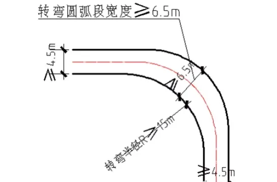
For rounded corners, straight road widths must be at least 4.5 meters, curved roads at least 6.5 meters, and turning inner diameters should be no less than 12 meters.
Roads must be solid and reliable. Construction sites should be leveled and reinforced, ensuring foundation bearing capacity meets requirements. Clear markings and signs must distinguish between load-bearing transport roads and temporarily hardened non-transport roads.
Regarding road bearing capacity: According to JTG D30-2015 “Code for Design of Highway Roadbeds,” medium or heavy traffic roadbeds must have a load capacity of at least 60 MPa. Also, JTG D40-2011 “Code for Design of Highway Cement Concrete Pavements” specifies that concrete surface thickness for heavy-load secondary roads should be between 220-260 mm.
Tower Crane Selection and Positioning
The choice of tower cranes for prefabricated concrete structures affects the lifting workflow and sequence due to the nature of prefabricated components. Tower crane placement is closely linked to construction flow division and direction. Beyond following general selection and installation guidelines, consider the following:
(1) Choose a tower crane capable of handling the heaviest prefabricated component’s weight and positioned to cover the maximum lifting radius.
(2) Verify the maximum weight and location of components expected to be lifted, and ensure the tower crane’s lifting capacity exceeds these demands with sufficient safety margins to accommodate unforeseen circumstances.
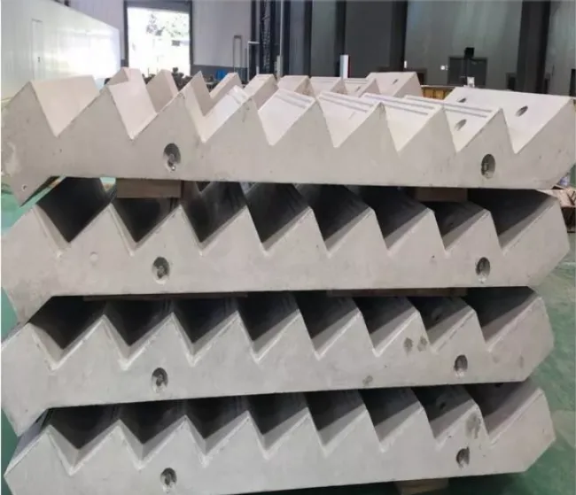
Component Stacking Requirements
Prefabricated composite panels, columns, and beams should be stacked properly:
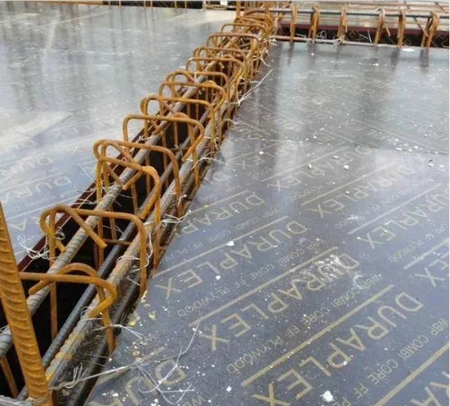
- Composite panels must not exceed six layers. Use four evenly sized wooden blocks as padding, ensuring the blocks are taller than the exposed stirrups.
- Columns and beams should be stacked no more than two layers, with flat, vertically aligned support pads placed underneath and between layers on a solid foundation.
- When stacking balcony panels and stairs, place four packs of yellow sand or wooden pads beneath to level height differences and prevent tilting or sliding.
Stacking of irregular prefabricated components should follow BIM guidelines and construction plans, adjusted to actual site conditions.
Part 2: Lifting Process
1. Construction Preparation
Personnel Preparation
Each lifting point requires seven installation personnel: one tower crane commander in the installation zone, one in the prefabricated component stacking area, four installation workers, and one installation commander in the installation area.
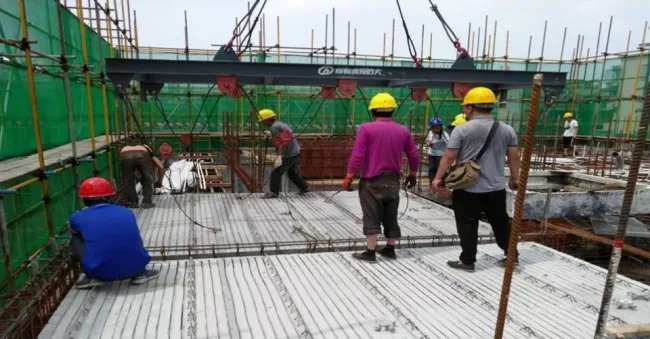
2. Prefabricated Composite Panel Hoisting
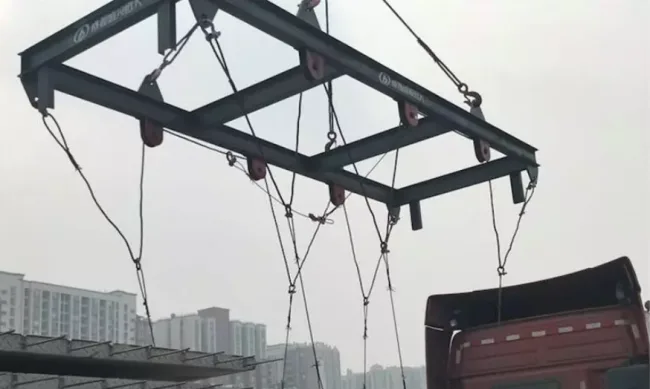
After transporting the laminated board to the designated lifting position, use a specialized cross-shaped lifting device designed for laminated boards. Confirm the laminated board’s identification number and dimensions before lifting. Once verified, attach the lifting hooks.
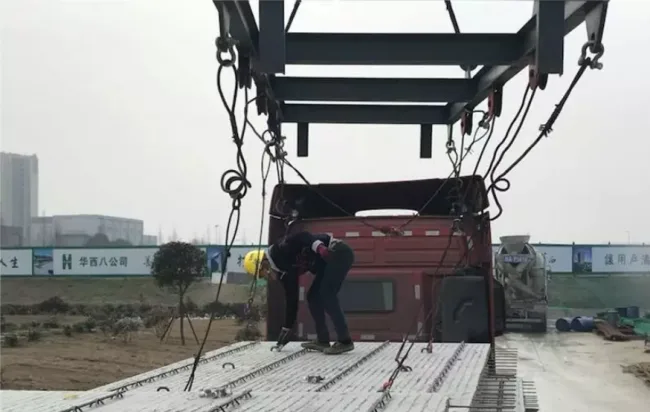
Command the tower crane to slowly retract the rope, ensuring even force distribution on the composite panel via the lifting pulley system. Double-check that the hook safety latch is secure and the steel wire rope is properly tensioned.
Before lifting, confirm that the installation area below is ready to receive the composite panels to ensure smooth installation and maintain lifting efficiency.
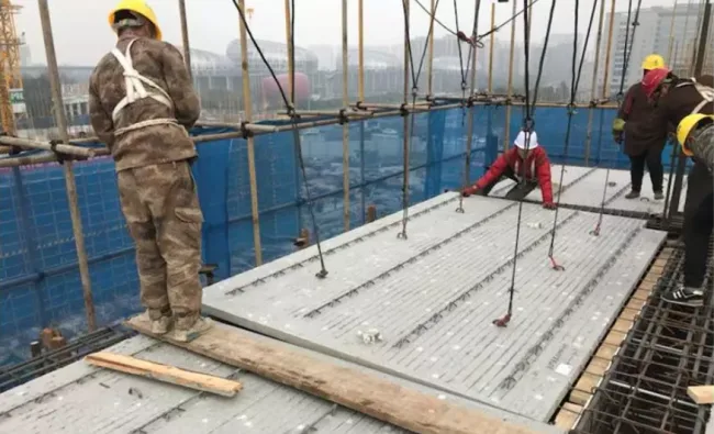
When the panel reaches about 1 meter above the installation position, pause to adjust its orientation and position to avoid errors after installation.

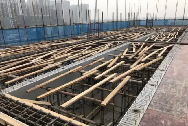
Before securing the panel, use pry bars and manual adjustment coordinated with the tower crane trolley to fine-tune its position. Ensure installation gaps meet drawing specifications, and overlapping structural panels entering beams align with design requirements.
3. Precautions
1. Cast-In-Place Beam Reinforcement
① If the prefabricated composite panel has two-way reinforcement bars only, leave one corner bar on one side of the cast-in-place beam untied temporarily, then tie the main bars after panel installation.
② If the panel is reinforced on all four sides, leave one corner bar untied on three sides of the beam temporarily, and tie the main bars after installation is complete.
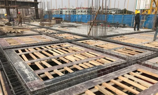
2. Setting Strips and Applying Adhesive Tape
① Install a 20-30 cm wide strip around the prefabricated composite panel to assist installation personnel and secure the beam formwork.
② Apply adhesive tape around the strip to prevent grout leakage.
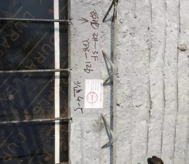
3. Identification of Panel Numbers, Directions, and Lifting Points
① Verify the numbering and dimensions of prefabricated composite panels before hoisting; lift only after confirmation.
② Refer to drawings during installation to ensure correct orientation and avoid discovering errors post-installation.
③ Strictly follow designated lifting points marked on the drawings, usually indicated by tied wires or paint marks. Unauthorized lifting points can cause panel cracking due to uneven stress.

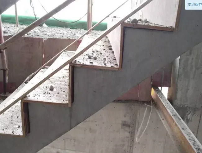
4. Stair Hoisting Procedure
1. Confirm that stair specifications and models are correct, check for quality defects, and verify lifting equipment integrity before installation.
2. Position adjustable hoists at the lower end of the stairs to facilitate angle adjustments.
3. Lift stairs horizontally and steadily to a certain height, adjust their angle with the hoist, and calibrate stair treads using a spirit level.
4. Safely lift the stairs to their designated installation position.
5. Align the stair installation holes with reserved steel bars on the stair beam, place the stairs accurately, make minor adjustments, then remove the lifting hook.
6. Install temporary supports after positioning.
7. Grout installation holes and fill gaps post-installation.
8. Protect the stair tread surfaces as finished products after installation.
9. Remove temporary supports only after grout strength reaches 85% of the design specification.
Source: Baidu Wenku, Chengdu Chengtou Yuanda, Douding Construction


Must log in before commenting!
Sign Up