1. Introduction
Some believe that steel reinforcement techniques for prefabricated concrete buildings are identical to those used in traditional cast-in-place concrete construction. This misconception often leads to insufficient attention to the unique procedures and technical training required for steel reinforcement in prefabricated structures. In reality, there are significant differences between the two.
For instance, in prefabricated concrete construction, steel reinforcement is typically processed into individual bars, which are then assembled into a steel reinforcement skeleton through binding or welding. This skeleton is hoisted into the formwork, where maintaining its shape is critical. Any deformation can alter the protective layer thickness of the steel, leading to cracks in the prefabricated components.
Moreover, the methods for connecting steel bars differ considerably. While traditional cast-in-place concrete relies mainly on welding, overlapping, and binding, prefabricated concrete employs connections such as grouting sleeves, mortar anchoring overlaps, and mechanical couplings. Ensuring high-quality steel bar connections is paramount in prefabricated concrete projects.
Professionals working with prefabricated concrete must thoroughly understand these characteristics and key aspects of steel reinforcement operations to produce qualified and superior steel reinforcement products, resulting in high-quality prefabricated components and overall construction excellence.
2. Differences in Steel Reinforcement Operations
When comparing steel reinforcement operations in prefabricated components to traditional cast-in-place concrete, several key differences emerge. These can be summarized into eleven points:
(1) The emphasis has shifted from on-site steel reinforcement fabrication to factory-based production. Prefabricated buildings involve breaking down the structure into components, which are primarily fabricated at the factory and then transported to the construction site for installation and connection.
(2) On-site steel reinforcement work now focuses mainly on connecting prefabricated components rather than fabricating steel bars. This includes connecting reinforcement between components (see Figure 1), reinforcing nodes, and some floor reinforcement work (see Figure 2).
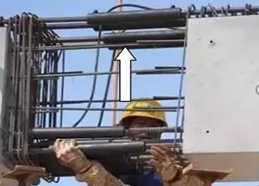
Figure 1: On-site Connection of Beam Reinforcement
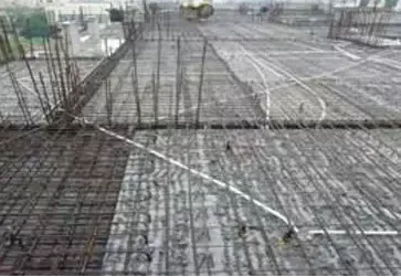
Figure 2: Construction Site Floor Reinforcement
(3) The quality of steel bar connections has become a central focus of quality control. Since prefabricated components are factory-produced with assured quality, the on-site installation—especially the steel bar connections—determines the overall structural quality (see Figures 3 and 4).
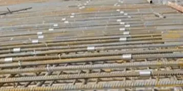
Figure 3: Mechanical Connection of Steel Bars
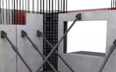
Figure 4: Reinforcement Binding Connection
(4) Steel bar processing is highly automated in factories, allowing for batch and efficient production compared to on-site processing (see Figure 5).
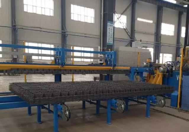
Figure 5: Automatic Processing Equipment for Truss Reinforcement
(5) The precision of steel bar fabrication has dramatically increased. Most bars are processed in factories using automated or semi-automated machinery, achieving millimeter-level accuracy (see Figure 6), significantly enhancing the finish quality compared to on-site processing.
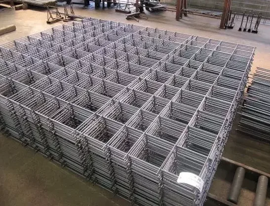
Figure 6: Steel Mesh Processed by Factory Automation
(6) Steel reinforcement work is closely coordinated with formwork. To maintain structural integrity, steel bars often protrude from prefabricated components, requiring corresponding holes or grooves in the formwork—a feature not present in cast-in-place concrete (see Figure 7).
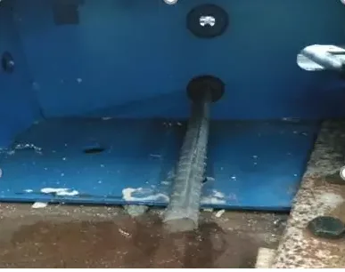
Figure 7: Holes for Protruding Steel Bars on the Template
(7) The precision requirements for the length and position of protruding steel bars are very stringent. These bars must align perfectly with sleeves or reserved blind holes on upper components to ensure reliable connections (see Figure 8).
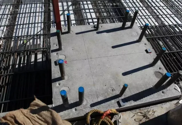
The length and position of steel bars extending from lower-level components must be highly accurate.
(8) The tolerance for omissions or errors is minimal. Embedded elements and protruding steel bars serve specific functions; any missing or misplaced items can hinder installation, compromise connections, or even render prefabricated components unusable.
(9) Measures must be taken to avoid interference between steel bars and embedded parts or objects. Proper coordination according to design and specifications is essential to prevent conflicts.
(10) Concrete cover requirements are stricter. To meet durability standards, factories enforce rigorous controls on the steel reinforcement protective layer during production (see Figure 9).
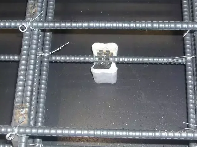
Figure 9: Reinforcement Protection Layer Spacer
(11) Attention must be paid to avoid collisions and interferences during on-site installation. Deviations in steel bar positions or conflicts with reserved locations can delay or complicate construction.
3. Key Points in Steel Reinforcement Operations
The unique characteristics of steel reinforcement in prefabricated concrete buildings define the critical points in processing and installation. The following aspects are essential to ensure quality and precision.
Important Aspects of Steel Bar Processing:
1. When extending steel bars through the formwork, precise holes or slots must be made. Accurate positioning and length are critical, and positioning devices can be used to prevent deviation (see Figure 10).
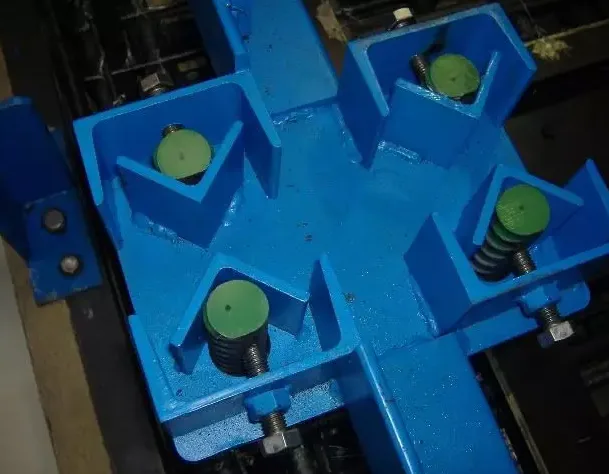
Figure 10: Positioning of Extended Reinforcement
2. The grouting sleeve is a crucial structural connection component. It is typically large in diameter and volume with a smooth finish. Reinforcement should be added around its periphery, and the protective layer thickness must comply with requirements.
3. To ensure the secure and reliable connection of embedded parts and objects within prefabricated components, reinforcing bars or other connectors are used to distribute forces and prevent pull-out or detachment. Due to embedded elements, steel bars may need adjustment to avoid shifting, bending, or cutting. Therefore, analyzing reinforcement and component diagrams before processing is necessary to adjust and ensure accuracy.
Key Points in Steel Reinforcement Skeleton Processing and Molding:
1. When transporting and lifting steel meshes or skeletons into the molds, multiple lifting points should be used to prevent deformation such as twisting, bending, or tilting (see Figure 11).
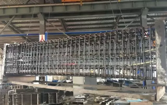
Figure 11: Four-Point Suspension of Column Reinforcement Skeleton (with Auxiliary Bottom Formwork)
2. During molding, steel bars should be straight, undamaged, and free of oil or contaminants. Handling must be gentle to avoid deformation.
3. After placing steel bars in the mold, overlapping areas—especially main and structural bars—should be protected to prevent contamination during concrete pouring, which could weaken bonding (see Figures 12 and 13).
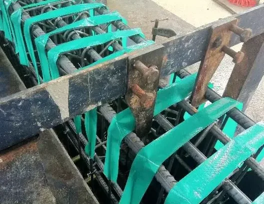
Figure 12: Reinforcement Protection of Composite Beam
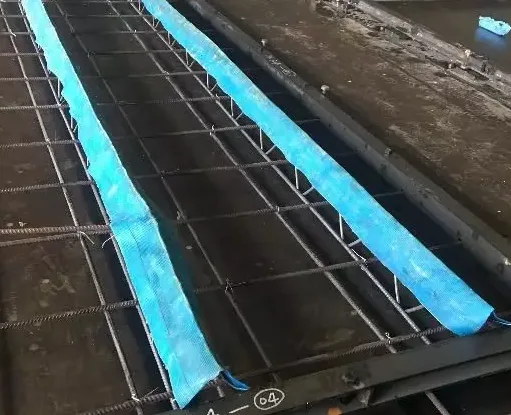
Figure 13: Protection of Composite Floor Truss Reinforcement
4. Installation of sleeves, embedded parts, and other steel bar connections must be precise, ensuring correct orientation, sealing, and firmness (see Figures 14 and 15).
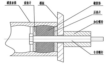
Figure 14: Schematic Diagram of Grouting Sleeve and Template Fixation
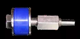
Figure 15: Grouting Sleeve Fixing Component
Key Points for Grouting Sleeve Component Installation:
Grouting sleeve connections are the most common method for joining steel bars in prefabricated concrete buildings. To ensure connection quality, installation must strictly follow operational procedures with attention to:
1. Checking the brand, type, and model of sleeves before installation. Sleeve specifications must match the steel bars, and the sleeves should be free from visible defects.
2. Ensuring the steel bar length extending into the sleeve meets design requirements. The connection must be straight, firm, and sealed to prevent grout leakage.
3. Installing sleeves perpendicular to the formwork, ensuring a tight, secure fit without grout leakage (see Figure 16).
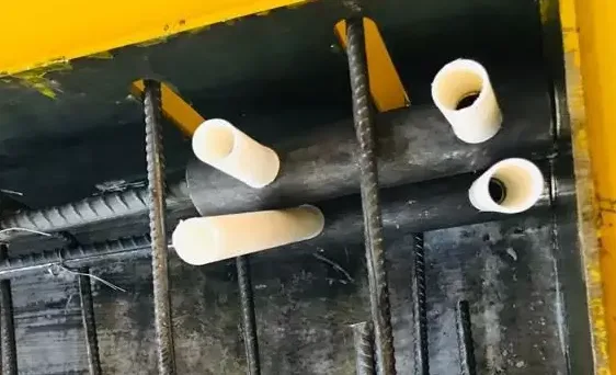
Figure 16: The Connection Between the Sleeve and the Template Must Be Tight and Firm
4. Grouting and grout outlet pipes must be securely attached to the sleeve’s grouting holes and outlets. Adhesives may be applied if necessary to ensure a solid bond.
5. Personnel responsible for threading steel bars in semi-grouted sleeves must be certified. The steel bar-to-sleeve thread connection must comply with relevant specifications.


Must log in before commenting!
Sign Up