Detailed Explanation of Prefabricated BIM Tutorial Structure Disassembly
1. Design of Prefabricated Components
Prefabricated structures are primarily characterized as cast-in-place equivalents. They consist of prefabricated columns, shear walls, composite beams, composite panels, stairs, balconies, and more. Due to their unique assembly, design adjustments differ slightly from traditional structures.
In prefabricated structures, secondary beams are often omitted to reduce assembly steps and simplify the construction process. When arranging beams and columns, it is essential to consider the dimensional limits imposed by the factory’s production equipment; otherwise, components may not be manufacturable. Shear wall layouts should facilitate easy disassembly during processing.
The load transfer method for floor slabs depends on the type of panel supplied by the manufacturer. Double-sided composite panels maintain their typical load path. However, if unidirectional prestressed composite or hollow panels are used, the load transfer must be adjusted to opposite-side and unidirectional transmission modes. Reinforcement design for slabs should account for non-primary stress directions via envelope design, considering cast-in-place thickness for two-way slabs.
When using software like PKPM for calculations, factors such as periodic reduction, beam stiffness increase, and torque reduction differ slightly from traditional design and require careful attention.
Construction drawings for prefabricated structures should minimize the number of sleeves in column or shear wall edge components to reduce costs. When laying out shear walls, besides following conventional shear wall principles, consider the following:
- (1) Use more L-shaped and T-shaped shear walls with fewer flanges, especially on exterior walls, to avoid scattered dismantling.
- (2) There are two approaches regarding flange lengths in shear wall structures:
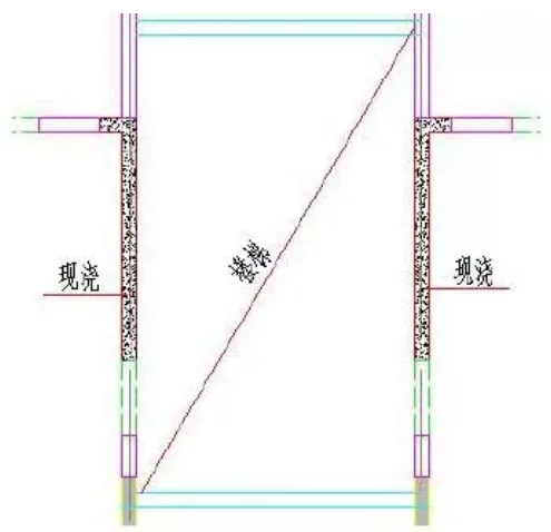
The first method involves maintaining a door/window stack of ≥ 200mm at openings, as illustrated in Figure 1. L-shaped exterior wall flanges typically have lengths ≤ 600mm, and T-shaped flanges ≤ 1000mm. This prevents issues with overly long edge components during pouring.
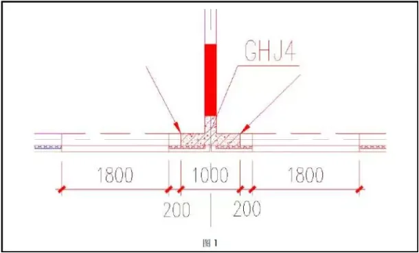
Notes:
- Window width is 1800mm, with a reserved 200mm stack for easy disassembly, and flange length is 1000mm.
- The arrow indicates floor height direction; steel bars between the beam and cast-in-place edge components are anchored, but no steel bars connect the 200mm window stack below to cast-in-place components. Only precast concrete connects to cast-in-place concrete, resulting in weaker seismic performance, but this does not compromise safety.
- When the window stack is ≥ 600mm, hollow external partition walls can be created, forming weak zones adjacent to cast-in-place edge components without compromising safety.
- Prefabricated specifications require edge components be cast-in-place, with window stacks generally ≥ 200mm; thus, a 200mm concrete stack is factored into the design.
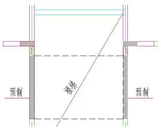
The second method allows L-shaped exterior wall flanges to be ≥ 600mm and T-shaped flanges ≥ 1000mm, with flange ends facing the window, shown in Figure 1-2:
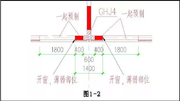
Notes:
- Window width is 1800mm; flange length is 1400mm, including 600mm cast-in-place and 400mm prefabricated sections.
- The external partition wall (including windows) is prefabricated with a 400mm shear wall, with steel bars anchored into 600mm of cast-in-place concrete.
- The arrow indicates floor height direction and connects with the 400mm prefabricated edge component as a whole. Due to the large window opening, this area is a weak point under seismic action and does not act integrally with the edge component, maintaining safety.
- (3) Connections between shear walls, partition walls, and beams primarily ensure sufficient beam anchorage length. Usually, 400mm cast-in-place (with 200mm thick walls) or prefabricated concealed columns are provided, so plane connections are generally reliable. Wall stacks extending from straight shear walls typically measure about 100mm to avoid excessive sleeves that complicate installation. Door or window piers should be ≥ 200mm or zero. When beam reinforcement uses anchor plates, longitudinal beam reinforcement should be ≤ 14mm (for 200mm thick shear walls).
- (4) When beams and walls are prefabricated together, lifting weights may be excessive, requiring longer shear walls.
- (5) If prefabricated components at door openings are too short, they can be combined with shear walls to extend shear wall length.
- (6) In shear wall structures, beams typically have two rows of reinforcement bars, regardless of cast-in-place or prefabricated. Theoretically, three 18mm bars can fit during cast-in-place, but concrete pouring constraints usually limit this.
- (7) When many pipelines are adjacent to electrical wells, the cast-in-place thickness is usually 60-80mm, commonly 80mm.
- (8) Keep column cross-sections uniform to maintain mold consistency, using the same number of columns with different diameters. The same applies to shear walls and connecting beams, preserving side formwork consistency.
- (9) Prestressing is most effective and economical when slab spans exceed 6m, primarily to control deflection. A combination of two-way composite panels (with truss steel bars) and single prestressed composite panels is generally recommended for cost efficiency.
2. Wall Splitting
(1) For prefabricated shear wall structures, when the length of external or internal shear walls in L or T shapes is ≥ 1000mm, the wall body (non-shaded areas) is typically prefabricated, while edge components are cast-in-place (shaded areas in Figures 1-5). External partition walls with beams are generally prefabricated, as shown in Figure 3.
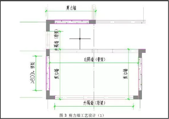
Notes:
- Cast-in-place edge components are designed considering two main factors: the force angle, as edge components are critical load-bearing parts requiring cast-in-place construction; and the fact that edge component ends typically support beams, with beam steel bars anchored there.
- If the prefabricated exterior wall is short with all window and door openings, it can be prefabricated together with adjacent shear wall edge components (hidden columns), allowing the cast-in-place portion to be shifted inward.
- If prefabricated lengths are short but lifting weights permit, shear walls can be prefabricated along with edge components and external partition walls with beams to reduce assembly numbers.
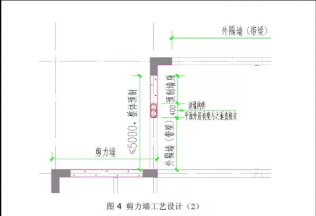
(2) When there are no beams perpendicular to hidden columns within the length of external or internal L or T-shaped shear walls, and lifting weight requirements are met, hidden columns can be prefabricated with adjacent external partition walls (with beams) and wall bodies, as shown in Figure 4.
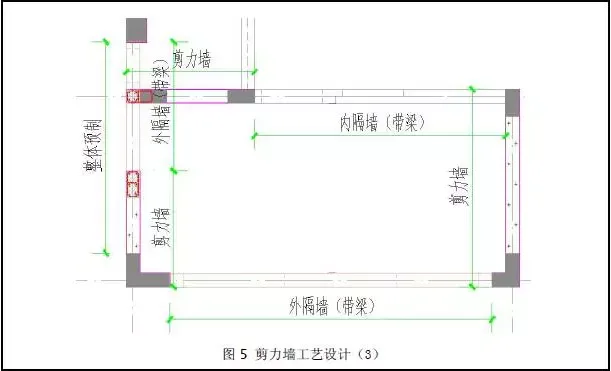
(3) When a shear wall intersects vertically on one side of an external or internal partition wall, and lifting weight requirements are met, the partition walls can be connected for easier lifting and construction. This connection with the shear wall is shown in Figure 5.
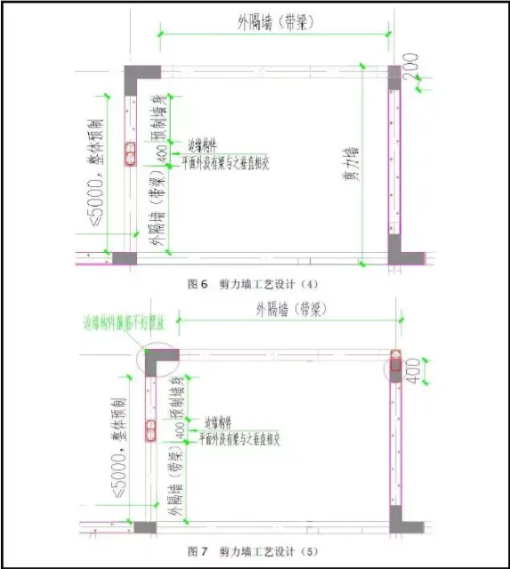
(4) For external shear walls designed for on-site assembly, the concealed column area (shown in Figure 6) is cast-in-place, leaving only 200mm construction space, complicating on-site work. An alternative design approach is shown in Figure 7.
(5) Shear walls at elevator shafts and staircases should always be cast-in-place.
(6) Connections between shear walls, partition walls, and beams mainly ensure beam anchorage length. BIM work usually confirms no plane issues because 400mm cast-in-place (200mm thick walls) or prefabricated concealed columns are common. Wall stacks extending from straight shear wall planes are generally 100mm. Door stacks should be ≥ 200mm or zero when prefabricated as a whole. Door and window stacks should be ≥ 200mm or zero (allowing for a “knife handle”). When beam reinforcement anchors via plates, longitudinal beam reinforcement should be ≤ 14mm (for 200mm thick shear walls). The cast-in-place concealed column position can be adjusted near the atlas-specified location.
3. Other Splitting Situations
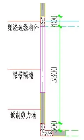
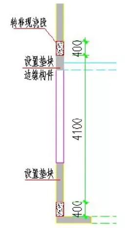
(1) In Figure 8, external partition walls in beam-partitioned walls transfer forces directly to the next beam layer, gradually accumulating downward. This force transfer does not match calculation models. Redesigning the project involves transferring the 400mm cast-in-place part and installing 20mm thick cushion blocks at intervals beneath the shear wall, eliminating beam partition walls and effectively resolving the issue, as shown in Figure 9.
(2) Casting the exterior wall of staircases in situ, as shown in Figure 10, can prolong construction and increase costs. In the project redesign, staircase-adjacent panels were thickened, and all shear walls on both sides of prefabricated staircases were prefabricated, effectively resolving these issues. The dismantling method is detailed in Figure 11.
Note: The dashed line indicates the extent of prefabricated stair sections.
(3) Low Prefabrication Rate
The Technical Specification for Prefabricated Concrete Structures allows edge components to be constructed using a combined “precast + cast-in-place” method.
Research has applied “XX technology” to edge component construction. By creating openings in prefabricated shear walls, the overall prefabrication rate improves. The updated wall dismantling design and process are illustrated in Figures 9, 11 to 13.
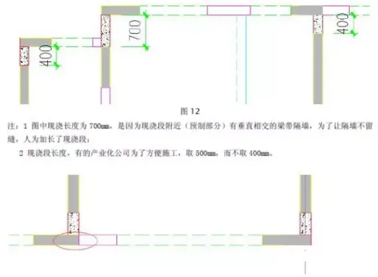
Note: Openings on edge components connect to composite beams through cast-in-place concrete.


Must log in before commenting!
Sign Up